English
 Türkçe

The large rotating mills in mining and cement plants (ball, rod, and autogenous mills) usually take their drive through a huge girth gear wrapped around the mill shell and a meshing pinion. The electric motor turning that pinion is one of the most critical pieces of equipment in the plant and has one of the toughest load profiles: hundreds of kW of power, very high inertia, heavy starting torque, and continuous heavy duty all combined. In this article we cover the power, torque, starting method, alignment, and durability criteria to consider when selecting a girth gear main drive motor. This content focuses on the girth gear/pinion drive meshing directly around the shell; a separate article covers the general selection of ball mill main drives.
How Does the Girth Gear and Pinion Drive Work?
The girth gear is a large-diameter gear ring, usually made of two halves, bolted around the outer circumference of the mill shell. The electric motor, through a reducer (or directly), turns a pinion; the pinion meshes with the girth gear and transmits low-speed motion to the mill shell with the high torque that the large diameter provides. This arrangement must produce very high torque to turn a load of hundreds of tonnes of material and grinding media (balls/rods).
The drive may be single-pinion, or at very high powers a dual pinion arrangement may share the load between two motors. Whichever arrangement is chosen, the fundamental challenges of motor selection are the same: overcoming inertia and load at start, running continuously at full load without overheating, and starting softly without damaging the gear mesh.
Why Is the Girth Gear Drive a Special Topic?
The difference between an ordinary industrial motor and a mill main drive motor is not only the size of the power. The girth gear drive is unique in the nature of the load the motor faces: the load has very high inertia, the start takes a long time, the speed is usually very low, and because the drive is transmitted through a gear mesh, torque fluctuations reflect directly onto the motor. These conditions require a special approach beyond standard motor selection logic. A wrongly selected main drive motor will either strain and overheat at start, jolt the gear mesh with shock load, or end its life early in continuous heavy duty. A correct selection, on the other hand, safeguards both production continuity and long equipment life. For this reason, the power, torque, starting, and protection criteria must be evaluated both separately and together.
Very High Starting Torque and Inertia
Starting a charged mill is one of the toughest scenarios a motor can face. The combined inertia of the shell, grinding media, and material load is enormous; moreover, the grinding media may be settled on one side of the shell (bedded), requiring an additional "lifting" torque at start. For this reason, the main drive motor must:
- Have high starting (breakaway) torque,
- Be thermally able to withstand the high current and heat drawn during starting,
- Not be damaged during the prolonged start time caused by high inertia.
We covered the relationship between rated torque and starting torque and correct selection by load in our article on IE3 motor starting torque and rated torque. For torque calculation from kW and speed, our article on IE3 motor rated torque calculation is useful.
High Power: Drives in the Hundreds of kW
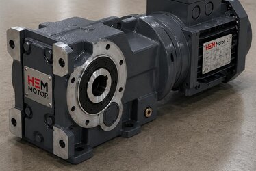
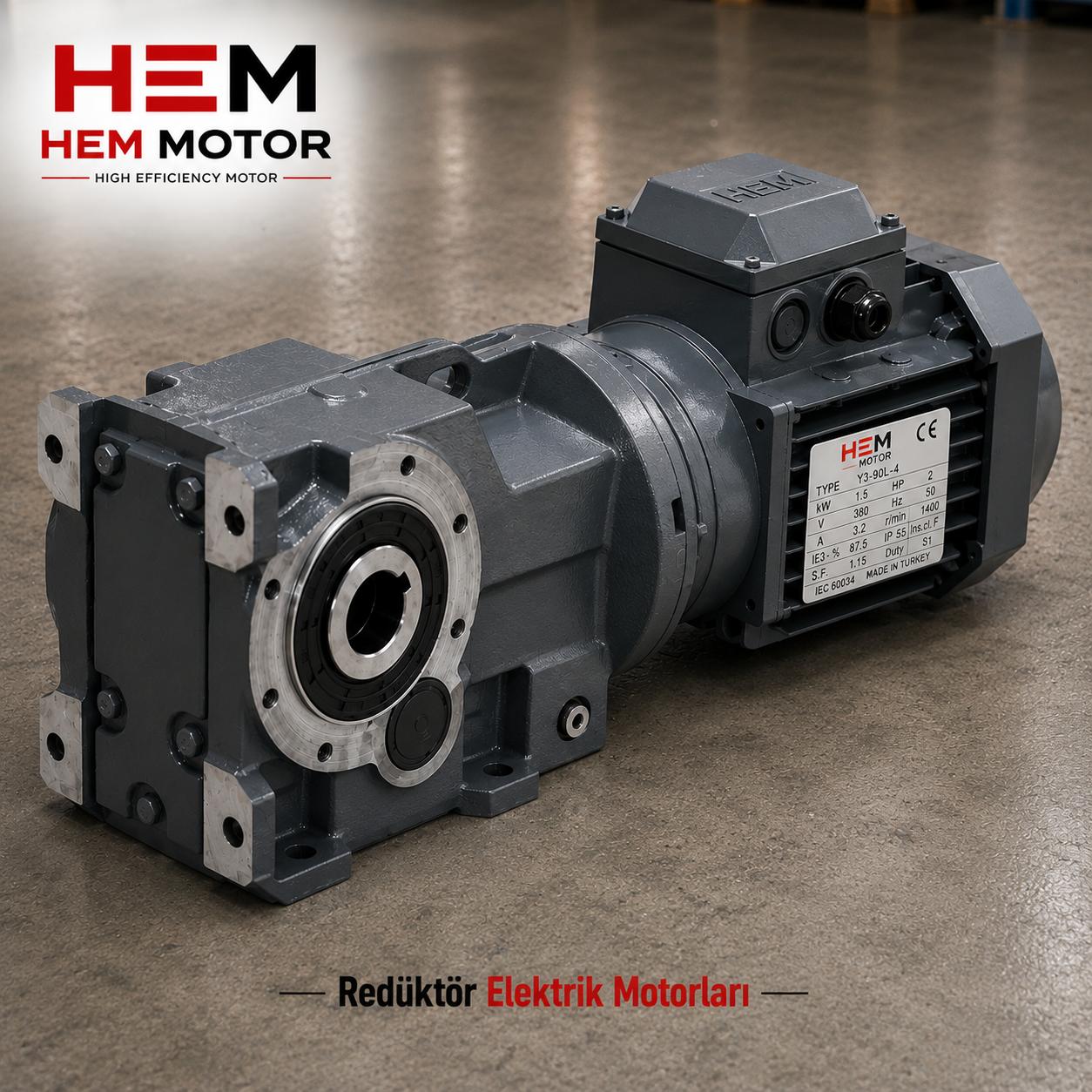
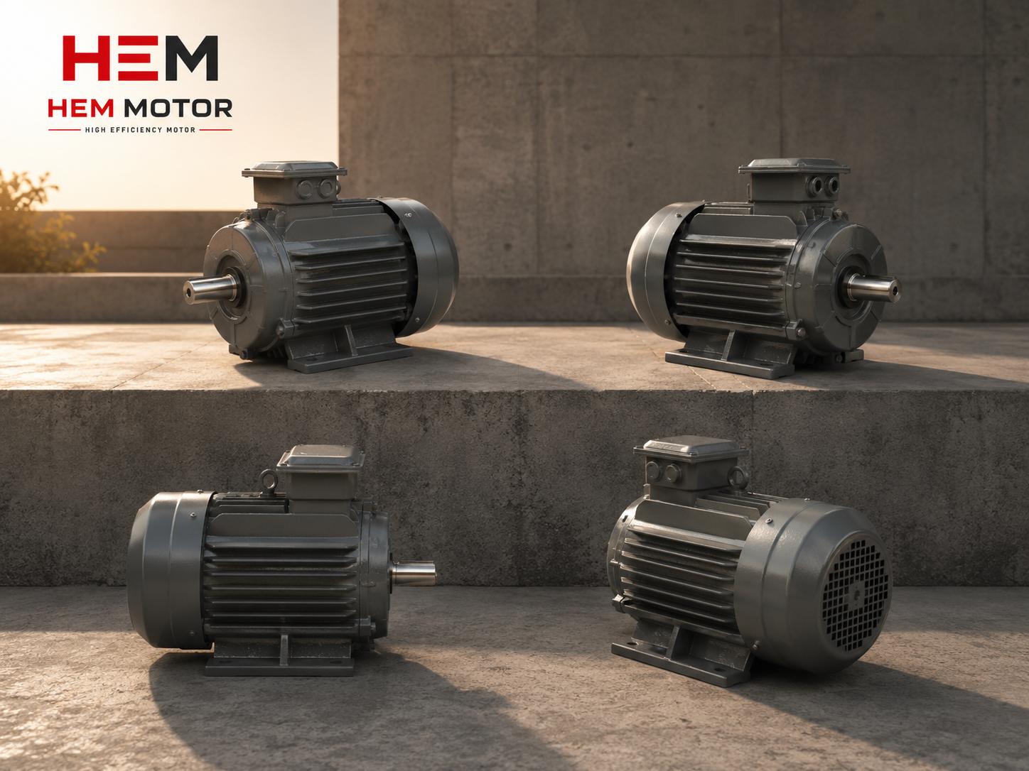
Industrial mill main drive motors are typically in the hundreds of kW and can go far higher in large plants. For mining applications, HEM Motor supplies cast iron body motors from 0.55 kW to 355 kW in IE3/IE4 efficiency class, suitable for high starting torque and high torque production; larger power needs are evaluated on a project basis. Key features of these motors:
- Cast iron body: Mechanical strength against shock, vibration, and heavy duty.
- 100% copper winding: Low heating and long life.
- Class F insulation, IP55 and above protection: Suitability for the dusty, humid mine/cement environment.
- Reinforced bearing structure: Resistance to high radial load and continuous operation.
You can find the general framework for high-torque, heavy-duty supply in mining and ore mills in our article on mine and ore mill motors.
Starting: LRS, Slip-Ring Motor, and Soft Starter
Because of high inertia and large power, direct-on-line (DOL) starting is often unsuitable for girth gear drives; the main reasons are the high starting current that stresses the grid and the sudden torque that jolts the gear mesh. The main methods used for soft, controlled starting:
- Liquid Resistance Starter (LRS) + slip-ring (wound rotor) motor: Provides the softest start under high inertia; starting torque is controlled by adding variable resistance to the rotor circuit. We explained this method in detail in liquid resistance starter (LRS) and slip-ring motor.
- Soft starter: On squirrel-cage motors, it limits starting current and torque by ramping up the voltage. For compatibility with IE3 motors, see IE3 motor soft starter compatibility.
- Frequency converter (drive): Fully controls speed and torque; it also enables slow turning of the mill for maintenance (inching).
For a comparison of starting methods on crushers and heavy drives, our article on crusher motor starting is also a useful guide.
Alignment and Gear Mesh
The life of the girth gear-pinion mesh depends heavily on correct alignment. Misalignment in the motor-reducer-pinion line causes uneven wear on the gear flanks, vibration, and noise. During commissioning and periodic checks, backlash, root/tooth contact, and the lubrication film condition must be monitored. On the motor side, it is critical that vibration and balance values stay within acceptance limits; we covered this in our article on electric motor vibration and balance ISO 10816 acceptance values. We examined the effect of flywheel and inertia under impact and variable load in motor selection under impact load.
Continuous Heavy Duty and Cooling
The mill main drive typically operates in S1 (continuous) duty, near full load for most of the day. This makes the motor heat management critical. Insufficient cooling shortens bearing and winding life. We detailed cooling and overheating management at continuous full load in our article on motor cooling and overheating, and duty-type selection in duty type (S1-S6) selection. PTC/PT100 protection is recommended to monitor winding temperature against the dust of the mine/cement environment.
Protection Against Dust, Moisture, and Field Conditions
Mining and cement plants create one of the toughest environments for an electric motor: heavy dust, moisture, temperature fluctuation, and vibration all combined. The girth gear drive motor usually works right next to the mill, at the point where these conditions are felt most intensely. For this reason:
- High IP protection class: IP55 and above against dust and moisture; higher protection is preferred especially at points with intense dust. We detailed dust sealing and protection class in crusher motor dust sealing and IP65/IP66.
- Winding temperature monitoring: Continuous monitoring with PT100/PTC against the risk of dust reducing cooling.
- Reinforced lubrication and sealing: Protecting bearings against dust and moisture directly affects life.
You can find the general protection approach against field conditions in stone quarry and mine site motor protection, and bearing life in terms of shock and dust in crusher and mill motor bearing life.
Downtime Cost and Spare Motor Strategy
The mill main drive is the heart of the plant's production line; a stop of this motor stops the entire grinding line. For this reason, in selecting the main drive motor, not only performance but also a spare strategy that can be brought online quickly in case of failure must be considered. Motors with standard IEC frame dimensions and common connection types provide a great advantage in replacement and spare-keeping; special/one-off solutions extend the supply time. We covered reducing motor failure and downtime cost in crusher and mill plants in crusher plant motor failure and downtime cost. Correctly storing and commissioning the spare motor during planned maintenance periods is also a critical matter.
Drive in the Specific Case of Cement Mills
In cement plants, raw material and clinker grinding mills are among the most common applications of girth gear drive. These mills are usually very large in diameter and high in power; there is an expectation of continuous, uninterrupted production. The fine and abrasive dust of the cement environment stresses both the motor protection and the gear lubrication. We covered the general framework of mill, fan, and conveyor motors in a cement plant in cement factory electric motors. In addition to the girth gear main drive, the mill feed, separator, and fan drives should be selected with the same efficiency and durability criteria.
Speed, Reducer, and the Drive Train
The mill shell turns at very low speeds; yet the speed range at which an electric motor runs most efficiently is much higher. To bridge this difference, a reducer (or the pinion-girth gear ratio) comes into play in the drive train. The high-speed, relatively low-torque motion from the motor is converted into high torque by reducing the speed at the reducer and gear stage. For this reason, in selecting the main drive motor, not only the motor but the entire drive train (motor + reducer + pinion + girth gear) must be sized together. The motor rated speed, reducer ratio, and girth gear-pinion ratio are matched so as to give the required mill operating speed. In this calculation, the efficiency and durability at every stage of the torque transmission chain must be considered. This structure, which produces high torque at low speed, is both energy-efficient and long-lasting when set up correctly.
Stock Supply and the Cast Iron Body Advantage
The cast iron body motors HEM Motor offers for mining and mill applications are designed to meet the requirements of this demanding environment. The cast iron body provides much higher mechanical strength than aluminium; it preserves body integrity under vibration, shock, and heavy duty. The 100% copper winding provides low heating and long life; class F insulation gives high temperature resistance. We covered the general advantages of insulation class in IE3 motor winding and insulation class (F/H) and the value of copper winding in copper winding vs aluminium winding. A main drive motor with the right power and the right protection ensures your plant's most critical equipment runs safely for years.
Frequently Asked Questions
Are girth gear drive and ball mill main drive the same thing?
Close, but not the same. Ball mill main drive is a general heading; the girth gear drive is the specific drive form where a pinion meshes with a gear ring wrapped around the outside of the shell. This article focuses specifically on the girth gear/pinion mesh and its unique requirements such as alignment, starting, and gear life.
Why is direct-on-line (DOL) starting not preferred?
Very high inertia increases the starting current and duration; also, the sudden torque of DOL jolts the huge girth gear-pinion mesh with shock load and shortens tooth life. For this reason, soft, controlled starting via LRS+slip-ring motor, soft starter, or drive is preferred.
When is a dual pinion needed?
A dual pinion arrangement is used when the torque a single motor can provide through a single pinion is insufficient, or when balanced load distribution is desired. In that case, the load sharing and synchronous operation of the two motors are managed by the drive control system.
Get a Quote for a Mill Main Drive Motor
At HEM Motor, we supply high-starting-torque, cast iron body IE3/IE4 motors together with starting solutions for mining and stone crushing plants. Let us determine the right power, torque, and starting method together for your mill girth gear main drive. For other mining applications and products, visit our homepage.
Get a Quote: Call us at +90 (532) 345 49 86 or reach us through our contact page.
Girth Gear Drive Motor Selection Checklist
- Have the charged-mill starting torque and inertia been calculated?
- Has the continuous full-load power (S1) been correctly determined?
- Has the starting method (LRS/slip-ring, soft starter, drive) been selected?
- Have the cast iron body and appropriate IP protection class been determined?
- Has the single-pinion vs dual-pinion decision been made?
- Is there a plan for motor-pinion alignment and backlash?
- Has winding temperature protection (PTC/PT100) been foreseen?
- Are vibration/balance acceptance values written into the specification?