English
 Türkçe
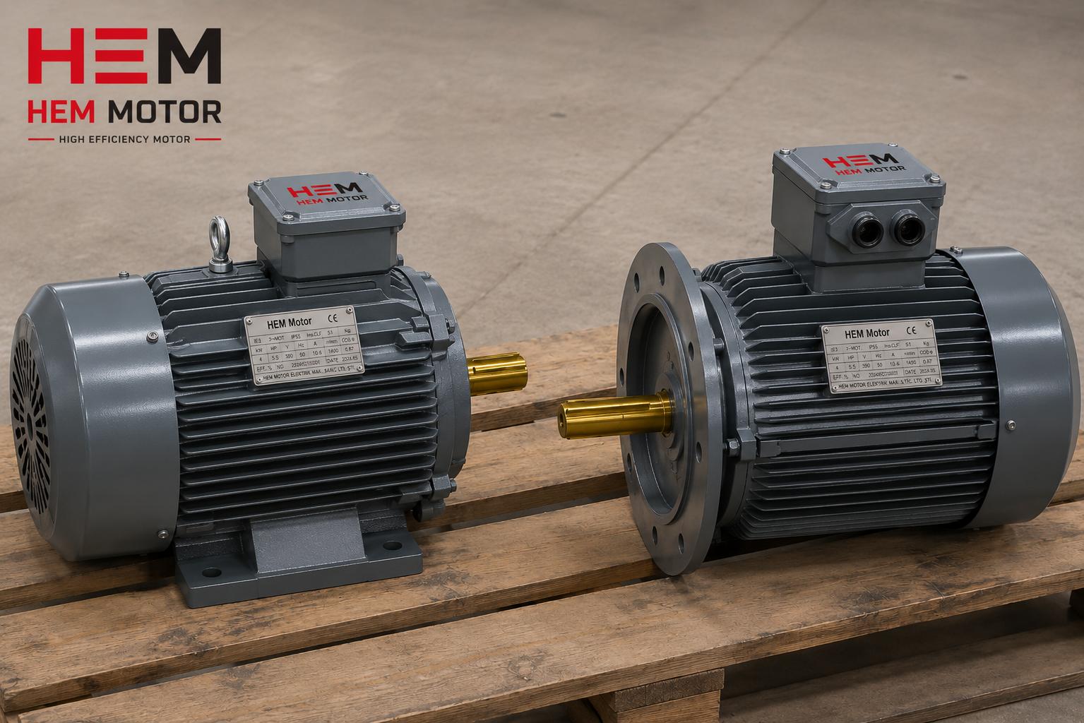
When moving a large cast iron asynchronous motor from the factory to the field, one thing is often overlooked: throughout the long transport period when the motor is not running and the shaft never turns, the rotor literally "bounces" inside the bearings. Every bump on the truck bed, every crane lift, every roll of the ship loads the weight of the stationary rotor onto the same contact point of the balls or rollers. The result is a subtle damage known in the industry as false brinelling, where tiny permanent marks form on the bearing raceways. When the motor arrives, it looks flawless, the nameplate is clean, the body is rock solid; but within the first weeks, increasing noise, vibration and premature bearing failure appear. This is exactly why, on heavy and large IEC frames, a transport rotor lock or shaft locking device is not a luxury but a mandatory part of correct shipping protection.
In this article we explain, in engineering but practice-oriented language, why the rotor is damaged during transport on large cast iron frame motors, the false brinelling mechanism, when a shaft locking device is required, how this lock that must absolutely be removed before installation works, and what to watch for when buying for correct shipping protection. The goal is to ensure that a solid motor leaving stock stays solid from its very first day in the field.
Why Is the Rotor Damaged in Transit? The False Brinelling Mechanism
When an electric motor runs, the rotor turns; the rolling elements inside the bearing (balls or rollers) constantly change position, the lubricant film is renewed and load is distributed to every point. When the motor is stopped and subjected to vibration, the picture reverses: the rotor does not turn, but the rolling elements oscillate back and forth on the micron scale under external vibration. This small oscillating motion breaks the lubricant film, metal-to-metal contact begins, and a series of bright/dull pits form on the raceway, spaced at the same pitch as the rolling elements. This is not true brinelling (indentation from static overload); because it is the joint product of vibration and wear, it is called "false" brinelling.
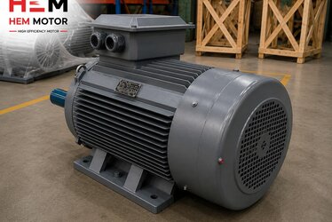
On large frames, the problem grows exponentially. In a cast iron motor with an IEC 280, 315 or 355 frame, the rotor mass can reach hundreds of kilograms. This heavy mass, while stationary, loads its entire weight onto the bottom few rolling elements of the bearing. The typical 5-50 Hz vibration band of a truck journey is exactly the frequency range where bearings are most exposed to damage. In short: the heavier the rotor and the longer and bumpier the transport route, the higher the false brinelling risk. The rigidity of the cast iron frame protects the motor from the outside but not the rotor inside; that is where the transport rotor lock comes in.
Which Bearing Type Is How Sensitive?
Not all bearings react the same to transport vibration. The table below summarizes the transit sensitivity and rotor lock need of common bearing types on large cast iron frames.
| Bearing / motor type | Transit sensitivity | Rotor lock need |
|---|---|---|
| Ball bearing (small-medium frame) | Medium | Usually not needed, advised on long sea routes |
| Ball bearing (large frame, heavy rotor) | High | Recommended |
| Cylindrical roller bearing (NU/NJ) | Very high | Mandatory |
| Sleeve (plain) bearing | Very high | Mandatory |
| Angular contact / high axial load | High | Recommended / mandatory |
Large motors with cylindrical roller bearings and sleeve bearings are the critical group. In a roller bearing, the line contact between the outer ring and the roller easily leaves marks under vibration while stationary. In a sleeve bearing, the rotor sits directly on the white metal bearing surface without an oil film forming (there is no film because the motor is not turning); every jolt creates a risk of indentation and notching on this surface. In these two groups, the manufacturer ships the motor from the factory with the rotor locked; installing without removing the lock is wrong.
How Does the Shaft Locking Device (Transport Rotor Lock) Work?
The transport rotor lock has a single job: to prevent the rotor from making relative movement inside the bearings during transport, that is, to fix the rotor relative to the frame. So when vibration arrives, the rotor and bearing move together and the rolling elements do not slide on the raceway. Several methods are used in practice:
- Shaft-end clamping block: A device bolted to the shaft end, usually on the drive side (D end), locking the rotor axially and radially. It is the most common method.
- Axial preload bolt: A bolt fitted into the threaded hole at the shaft center, lightly pressing the rotor toward one bearing and zeroing the axial clearance.
- Fan/cowl side lock: In some designs the rotor shaft is fixed from the N end with a bracket mounted to the cowl.
- Internal spacer/chock: On large sleeve-bearing motors, internal chocks that prevent axial movement of the rotor and are removed at installation.
A well-designed lock is usually painted in an eye-catching color (mostly red or yellow) and carries a "REMOVE BEFORE OPERATION" warning. The reason is vital: if the motor is started without removing the lock, the rotor is forced to turn, the lock device breaks, the shaft can bend, and the coupling or load side is damaged. That is why the lock is, alongside being shipping protection, an installation checkpoint.
Removal Before Installation and Storage
The rotor lock is not single-use packaging; in most cases it should be kept for future re-transport of the motor (overhaul, relocation, storage). The correct workflow is:
- Place the motor in the field, make the foot or flange connection but do not yet connect the coupling.
- Remove the rotor lock and verify the shaft turns freely by rotating it a few turns by hand.
- Label the removed lock device with its bolts and store it with the motor documents.
- On motors to be stored long term, periodically turn the rotor by hand a few turns (for example monthly); this changes the bearing contact point and lowers false brinelling risk.
Correct Shipping Protection: What to Watch When Buying
When buying a large cast iron frame motor, shipping protection is as important as the nameplate values. For correct supply, clarify these points:
- Learn the bearing type: If you are ordering a large motor with roller or sleeve bearings, confirm the rotor lock comes installed as standard.
- State the transport mode: On long road, sea or multi-transfer shipments, clearly state your rotor lock requirement.
- Question the packaging: Bolted fastening on a wooden pallet, a moisture barrier and shock absorption complement the rotor lock.
- Position lock/axial clearance: On sleeve-bearing motors, verify that the axial position is preserved in transit.
- Documentation: Make sure the lock removal instruction is in the motor documentation.
If you want to go deeper into cast iron frame selection and large motor mechanics, our articles on cast iron motor frame sizes and weight handling and impact, rigidity and vibration in cast iron motors are a good start. On the bearing life and storage side, cast iron motor bearing and bearing life and motor storage, holding and bearing protection integrate the transport-storage chain. For the shaft-load relationship, see our guide on shaft radial-axial load and bearing limit.
Frequently Asked Questions
Must every large motor have a transport rotor lock?
No. Small and medium frame, ball-bearing motors usually do not need one on short road shipments. However, large frames with heavy rotors, motors with cylindrical roller or sleeve bearings, and long/sea shipments practically require a rotor lock. The decision is determined jointly by bearing type, rotor weight and transport distance.
What happens if I forget to remove the rotor lock?
When the motor is started, the rotor is forced to turn; the lock device can break, the shaft can bend, the bearing and coupling are damaged, and overcurrent protection on the drive/grid side may even trip. That is why the lock is painted in an eye-catching color and carries a "remove before operation" warning. Add a "rotor lock removed?" item to your installation checklist.
Can a motor be used if false brinelling has occurred?
Light marks may tolerate operation for a while, but these points become the seed of noise, vibration and accelerated bearing fatigue. On a motor with clear false brinelling, the most correct solution is bearing replacement. The most economical route, however, is to prevent the damage from the start: a correct rotor lock and shipping protection.
Detecting Damage Early in the Field and Commissioning Checks
The insidious side of transport-induced bearing damage is that it cannot be seen by eye when the motor arrives. That is why, on large cast iron frame motors, a series of checks before commissioning and during the first run are critical to catch the early signs of false brinelling. The first step is to feel the axial and radial clearance of the shaft before removing the rotor lock; excessive clearance or binding is a sign that position may have been lost in transit. After the lock is removed, the shaft is turned a few full turns by hand; a smooth, even rotation is expected. A recurring catch or "clicking" felt at each turn is an early warning that a mark may have formed on the rolling path.
On the first electrical run, the motor is turned unloaded, with the coupling not yet connected. Taking a vibration measurement at this idle is worth gold in the field. In the vibration spectrum taken from the bearing area, distinct peaks at the harmonics of the rotation frequency or at the bearing passing frequencies indicate developing bearing damage. Likewise, a bearing temperature above normal and rising rapidly in the first hours is a sign of dry friction or a damaged surface. In the field, these simple checks allow a fault that would later cause a production stoppage to be caught months in advance.
Commissioning Checklist
- Record whether there is any impact mark, tip sensor trigger or damage on the packaging and pallet.
- Before removing the rotor lock, check the axial/radial clearance; note any anomalies.
- Remove the lock and verify smooth rotation by turning the shaft by hand.
- Before connecting the coupling, measure vibration and noise in an unloaded run.
- Monitor the bearing temperature and vibration trend in the first hours.
- Label the removed rotor lock and keep it for future transport.
Storage, Re-transport and Long-term Holding
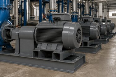
The value of the transport rotor lock is not limited to the first shipment only. Large cast iron frame motors are often held in stock as spares; they are relocated during a line overhaul or sent to another plant. Every re-transport carries the same false brinelling risk as the first shipment. That is why the removed lock device, its bolts and the removal instruction should be kept with the motor documentation; when the motor is to be transported again, it should be refitted. On a motor waiting long in stock, if the rotor stays at the same bearing contact point for weeks, false brinelling can begin even in a slightly vibrating storage environment. The simplest way to prevent this is to turn the rotor periodically by hand and change the contact point.
The mass of the cast iron frame brings, along with the storage advantage, a responsibility too: the heavier the motor, the higher the static load the stationary rotor places on the bearing. For this reason, on large motors held as spares, moisture protection in line with the manufacturer's storage instruction, use of a space heater and periodic rotor turning directly affect bearing life. A correctly stored and correctly transported motor runs as solid as on day one the day it comes off the shelf; a wrongly held motor can reach the field with bearing damage without ever having run.
The Difference Between True Brinelling and False Brinelling
Field teams often confuse these two damages, but their causes and remedies differ. True brinelling is the permanent plastic deformation (indentation) created when a static overload applied to the bearing presses the rolling elements into the raceway; for example, forcing the motor by its shaft with a hammer, fitting the coupling with a blow or pressing the bearing wrongly creates this damage. False brinelling, on the other hand, is not load but the small vibratory movement in the stationary state breaking the oil film and creating wear; this is the typical damage of transport. Both leave regularly spaced marks on the raceway, but while true brinelling forms instantly with a single blow, false brinelling accumulates over time with vibration.
This distinction matters in the field because the solution differs. To prevent true brinelling, correct installation technique (heat fitting, the right press tool, not striking the shaft) is enough. To prevent false brinelling, the transport and storage process must be controlled, that is, a rotor lock must be used and the rotor turned periodically. Managing both risks at once on a large cast iron frame motor is the only way to carry the motor's expected life to the field.
The Rotor Lock and Liability in the Shipping Contract
An overlooked issue in the supply of large motors is who is responsible for bearing damage occurring during transport. If the motor manufacturer fits the rotor lock correctly and ships it with the correct instruction, the damage is usually related to the transport or commissioning stage, with the lock removed wrongly or never fitted. For this reason, clearly writing the rotor lock requirement, the packaging standard and the checks to be made during commissioning into the purchase contract protects both buyer and supplier. Especially on multi-transfer international shipments, the use of packaging with tip and impact sensors allows liability to be determined objectively.
If you want to receive your large cast iron frame motors with correct shipping protection, a rotor lock and proper packaging, HEM Motor is by your side with its stocked product range and fast delivery advantage. For a solution suited to your bearing type, frame size and transport conditions, contact us and request a quote; let a motor that leaves solid for the field run solid from its very first day.