English
 Türkçe
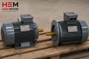
Cast iron framed brake motors are used in conveyors, cranes, hoists and vertical drives where the load must be held safely. They are equipped with a spring-applied electromagnetic brake that engages the instant power is lost. This brake is normally fail-safe: when the coil is energised the brake releases, and when power is removed the spring forces the friction lining against the disc, locking the shaft. However, there are situations where you must release the brake by hand — during maintenance, manual positioning, rescue, or an electrical fault. This is where the manual hand release lever comes in. Choosing the correct lever type, measuring lining wear, adjusting the air gap and setting the brake torque correctly are all critical for both operator safety and plant continuity.
In this article we cover, in practical terms, how the manual release lever works on a cast iron brake motor, the difference between lockable and self-returning lever types, how to measure lining wear, how to adjust the air gap, brake torque staging, and routine maintenance steps. The goal is to help you order the correct brake option when purchasing the motor and to use the brake safely in the field.
What Is a Manual Release Lever and Why Is It Needed?
The spring-applied electromagnetic brake is a safety device that closes automatically when power is lost. But if a power failure occurs while a load is suspended, the brake must be temporarily released to lower the load to a safe point. The manual release lever mechanically separates the lining from the disc without energising the coil, allowing the shaft to turn freely. In crane and hoist-type lifting applications this lever is a rescue function and, per standards, must be accessible.
On a brake motor without a release lever, the only ways to lower a load during an electrical fault are to feed external supply to the brake coil or to dismantle the brake; both waste time and create risk in the field. For lifting and vertical applications the release lever option must always be specified.
Lever Types: Lockable and Self-Returning
The manual release lever is offered in two basic types and must be selected according to the application:
- Self-returning lever: The operator pulls the lever, the brake releases; when released, a spring automatically returns the lever and the brake re-engages. The load is free only while the lever is held by hand. This is the preferred type for safety; when the operator lets go, the load stops (hold-to-run logic).
- Lockable / latching lever: The lever can be latched in the open position, keeping the brake released during maintenance so the shaft can be turned freely. It should only be used when the load is safe and for maintenance; leaving it latched while a load is suspended is dangerous.
In crane and hoisting applications a self-returning lever is generally mandatory. In horizontal conveyor and maintenance applications a lockable lever adds convenience. Duty type is also decisive in correct brake motor selection; see our guide on braked and variable-load duty types.
Lining Wear Measurement and Air Gap Adjustment
The friction lining (friction disk) wears over time. As the lining thins, the air gap between the armature plate and the coil body increases. When this gap exceeds a defined limit, the coil can no longer pull the armature when energised; the brake fails to release or operates noisily (humming). The air gap must therefore be measured periodically with a feeler gauge and reset to the nominal value.
The table below gives general reference values for nominal air gap, maximum gap and minimum lining thickness for typical IEC brake sizes. Always check the motor and brake nameplate for exact figures.
| Brake Size (approx.) | Nominal Air Gap (mm) | Max Air Gap (mm) | Lining Min. Thickness |
|---|---|---|---|
| Small (≈ 71-90 frame) | 0.20 | 0.50 | ~50% of new lining |
| Medium (≈ 100-132 frame) | 0.30 | 0.60 | ~50% of new lining |
| Large (≈ 160-200 frame) | 0.40 | 0.80 | ~50% of new lining |
| Very large (≈ 225+ frame) | 0.50 | 1.00 | Per manufacturer limit |
Air gap adjustment is usually done with adjusting nuts or screws: tightening the nuts reduces the gap. If the gap reaches the maximum value and the adjustment range is exhausted, the lining must be replaced. A lining beyond the wear tolerance causes the brake torque to drop, overheating and uncontrolled slipping.
- Always measure with the brake in the closed (de-energised) position.
- Pass the feeler gauge at several points to check for uneven wear.
- After adjustment, cycle the brake a few times and re-measure the gap.
- Oil/grease contamination on the lining drastically reduces torque; clean or replace.
Brake Torque Adjustment
Brake torque is determined by how hard the springs press the lining against the disc. In most electromagnetic brakes the torque can be adjusted in steps by changing the number of springs or the spring pre-load. The correct torque is typically chosen as 1.5-2 times the motor rated torque; in lifting applications the safety factor is kept higher.
Excessively high torque causes harsh stops, mechanical shock and excessive lining/disc wear. Low torque means the load slips and the stopping distance lengthens. When ordering a brake motor, stating the application torque and stopping precision lets the correct spring stage be set at the factory. For correct ordering of brake motor accessories, our guide on brake, encoder and forced cooling fan accessories will be helpful.
DC and AC Brake Difference
The brake coil can be DC or AC supplied. DC brakes respond more quietly and precisely but require a rectifier; AC brakes are simpler but noisier. For spring-applied DC/AC brake type selection on induction brake motors, see our article on spring-applied brake type and torque selection.
Maintenance Steps and Periodic Inspection
- Measure the air gap periodically; reset to the nominal value.
- Check lining thickness against the minimum limit; replace at the limit.
- Operate the release lever mechanism by hand at every service; verify the self-returning lever's return.
- Keep the brake disc surface clean of oil/moisture contamination.
- Measure coil resistance and rectifier output to check electrical integrity.
- Verify the tightening torque of bolted connections.
Regular maintenance extends the brake motor's life and prevents unexpected stoppages. The bearing and journal life of the cast iron frame also directly affect brake motor reliability; our article on bearing and journal life in cast iron motors guides the purchasing decision.
How to Order the Correct Brake Option?
When ordering a cast iron brake motor, state these clearly: brake torque (Nm), release lever type (self-returning / lockable), brake supply type (DC/AC and voltage), whether you want the brake wired in the terminal box, the need for a micro-switch (lining wear / brake position monitoring), and the application duty type. This information lets the motor arrive ready for the field.
Brake and Lining Monitoring with a Micro-Switch
In critical lifting applications it is desirable to monitor electrically whether the brake has actually released or closed, and whether the lining has reached its wear limit. For this a micro-switch (limit switch) option is added to the brake. Two types are common: a brake position monitoring switch (armature pulled / not-pulled signal) and a lining wear switch (signals when the lining reaches the wear limit). These signals are carried to a PLC or control panel to raise an alarm on brake fault, preventing surprise slipping while a load is suspended.
When ordering a brake with a micro-switch, specify the switch type (NO/NC), the contact current/voltage rating, and whether it is terminated in the terminal box or a separate signal box. This option is valuable for predictive maintenance and safety integrity.
Brake Selection for Vertical (V1) Mounting
In vertical (V1) mounting with the shaft pointing down, the brake holds the load against gravity and the release lever is vital. In this mounting the brake torque reserve should be chosen higher, the release lever must be of the self-returning type, and extra protection (deflector, V-ring) should be considered to keep oil/grease off the brake disc surface. The cast iron frame provides mechanical rigidity in vertical mounting, reducing vibration and alignment drift. For correct frame-to-power matching, our article on frame size and power matching guides selection from stock.
Brake Operating Principle: Step by Step
Understanding how the spring-applied electromagnetic brake works is fundamental both to selecting the correct option and to troubleshooting in the field. The process works as follows: when the motor is energised, the brake coil is also supplied with voltage and the coil creates a magnetic field. This field overcomes the spring force and pulls the armature plate towards the coil body. When the armature is pulled, the lining is released, the disc and therefore the shaft turn freely; the brake is open. When the motor power is removed, the coil field collapses, the springs push the armature, force the lining against the disc, and the shaft locks; the brake is closed. This "closes when power is lost" logic is why the brake is fail-safe: in a cable break or power loss, the brake engages by itself and holds the load.
The manual release lever is a mechanical intervention in this chain: even without coil power, the lever mechanically pulls the armature back, separates the lining from the disc and releases the shaft. The brake can thus be opened by hand without electricity. Correct adjustment of this mechanism requires the lever to be neither too loose (risk of accidental release) nor too tight (cannot release).
Brake Disc and Lining Material
Brake performance depends largely on the friction material. In modern electromagnetic brakes the lining is made of asbestos-free organic or sintered friction material. The material choice is made by friction coefficient, thermal endurance, wear resistance and operating environment. In applications with high-frequency stop-start (e.g. frequently stopping conveyors) the lining heats up; in this case heat-resistant material and, if needed, brake cooling should be considered. Since the friction coefficient drops in humid or oily environments, the brake disc surface must be kept clean and, if necessary, an enclosed (IP-protected) brake should be chosen.
The lining wear rate is proportional to the energy dissipated per stop (load inertia and speed), the stop frequency and the brake torque. In an application that frequently stops a high-inertia load at high speed, the lining wears quickly; this requires more frequent wear checks and a larger brake selection. When ordering a brake motor, stating the stop frequency and load inertia ensures the correct brake size is selected. The bearing load and mechanical life of a brake motor also depend on the application; our article on shaft diameter, key and coupling matching addresses mechanical compatibility.
Brake Response Time and Stopping Distance
How quickly a brake closes (response time) directly determines the stopping distance in lifting and safety applications. The brake response time depends on how quickly the coil's magnetic field collapses and varies with the supply arrangement. In DC brakes, if the coil is interrupted on the DC side (with fast-cut/over-excitation circuits) the response is very fast; if interrupted on the AC side, the field collapses more slowly and the stop is delayed. In safety-critical applications a fast-acting circuit is used to shorten the stopping distance.
- Slow cut (AC side): longer stop; soft but delayed.
- Fast cut (DC side / fast-acting): short stop; for safety applications.
The stopping distance calculation depends on load inertia, speed and brake torque. In applications requiring precise positioning or safety stopping, these parameters must be specified at order time.
Frequently Asked Questions
Is the manual release lever standard or an option?
With most manufacturers the release lever is an option and must be specified when ordering. In crane, hoisting and vertical applications a self-returning lever is practically mandatory. On horizontal conveyors a lockable lever is preferred for maintenance ease. Stating the application type at order time ensures the correct lever is fitted at the factory.
What happens if the air gap grows?
As the lining wears the air gap grows; once it exceeds a defined limit the coil cannot pull the armature and the brake fails to release or runs noisily. The brake then overheats, torque drops and the load can slip. The gap must be measured periodically with a feeler gauge, reset to nominal with the adjusting nuts, and the lining replaced once the adjustment range is exhausted.
Can I change the brake torque in the field?
Most electromagnetic brakes allow stepped torque adjustment by changing the number of springs or pre-load. However, torque adjustment must match the application requirement and safety factor. Incorrect torque causes harsh stops or load slipping. If in doubt, tell us the application torque and let us set the correct spring stage at the factory.
At HEM Motor we supply cast iron framed brake motors with the correct release lever type, adjusted brake torque and wear-monitoring options — from stock and with fast delivery. Send us your application's torque, duty type and rescue requirements; request a quote for the right brake configuration and let us determine the suitable motor for your project together.