English
 Türkçe
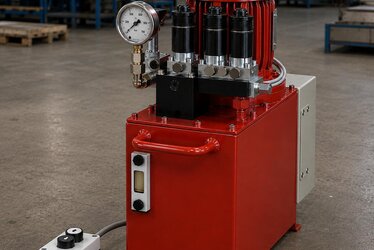
You don't want a conveyor belt to spill its load when it stops, a crane load to drift downward while suspended in the air, or an automatic door to coast freely as it closes. This is exactly where an asynchronous brake motor comes in. Integrated into the rear of a standard induction motor, the spring-applied electromagnetic brake engages the instant power is removed, holding the shaft safely. In this article we walk step by step through how a brake motor works, the difference between a DC brake and an AC brake, how to select the brake torque as a ratio of rated torque, the need for fast stopping and load holding, the manual release (hand release) mechanism, and correct brake motor selection for conveyor, crane and door applications. At HEM Motor our goal is to help you choose the right brake torque and brake type the first time, because a wrongly sized brake either fails to hold the load or produces needless wear and noise.
What Is an Asynchronous Brake Motor and How Does It Work?
An asynchronous brake motor is a classic three-phase (or single-phase) induction motor with an electromagnetic disc brake added to its rear endshield. The principle can be summed up in one sentence: open when powered, closed when unpowered. This is called a spring-applied (fail-safe) brake and it is critical for safety. When the motor is energized, the brake coil is energized too; the magnetic force pulls the pressure plate back against the springs and releases the disc, so the motor turns normally. When power is removed (a stop command, emergency stop, or power failure), the coil loses its energy, the pressure springs push the disc against the friction linings, and the shaft is braked instantly. In short, the brake engages even during a power cut, which is indispensable in load-holding applications.
The brake disc is usually coupled to the motor shaft via a key or hub and can slide axially. Friction torque is generated between the fixed lining surfaces and the disc. The magnitude of this friction torque depends on the spring force and the lining friction coefficient. What the brake must do (just hold, or rapidly stop a moving load) determines your choice.
The Spring-Applied (Fail-Safe) Brake Logic
The spring-applied brake is the most common safe brake type in industry. Its advantage is that the brake closes automatically on any loss of power. That makes it the standard choice in applications where the load could run back, such as hoisting, lifting and inclined conveyors. The release (opening) time and the engagement (braking) time vary with brake type and supply method; these times matter especially where fast, precise stopping is required.
DC Brake or AC Brake? Choosing the Right Supply Type
The electromagnetic brake coil is supplied with either direct current (DC) or alternating current (AC). The difference directly affects the brake's reaction speed, noise and service life. Most modern brake motors operate as DC brakes via a bridge rectifier, because a DC coil is quieter, more stable and longer-lived. An AC brake releases faster directly from the mains, but its hum and vibration are more pronounced.
| Feature | DC Brake (Rectified) | AC Brake (Direct) |
|---|---|---|
| Supply | DC coil via bridge rectifier | Three/single-phase AC coil |
| Noise/hum | Low, quiet operation | Higher, slight hum |
| Release speed | Medium (separate switching can speed it up) | Fast |
| Braking response | Very fast if DC side is switched | Fast |
| Life and stability | High, stable torque | Medium |
| Typical use | Conveyor, general industry, precise stopping | Special cases needing very fast response |
An important practical point: switching the DC brake coil only on the motor's AC side can slow the brake's engagement, because the coil inductance keeps current flowing for a while. When fast and repeatable stopping is required, the brake is also switched on the DC side (via a separate contact). This detail significantly shortens the stopping distance, especially in precise positioning and frequent start-stop applications. Our article on DC and dynamic braking in induction motors is a complementary resource on braking and stopping strategies.
Brake Torque Selection: Ratio to Rated Torque
The heart of brake motor selection is brake torque. Brake torque (Nm) expresses the torque the brake can hold or stop, and it is usually given as a ratio to the motor's rated torque. The general engineering approach is:
- For holding-only applications, brake torque is chosen at least 1.5-2 times the static load torque; the load must not slip when stopped.
- Where dynamic stopping (stopping a moving load) is required, brake torque is often selected around 1.5-2 times the motor's rated torque, giving a short and repeatable stopping distance.
- For inclined conveyors and lifting, where the load may run back, brake torque must exceed the run-back torque with a safe margin.
| Application | Recommended Brake Torque (× Rated Torque) | Priority |
|---|---|---|
| Horizontal conveyor (general) | ≈ 1.0 - 1.5 × Mn | Positioning + short stop |
| Inclined conveyor | ≈ 1.5 - 2.0 × Mn | Prevent run-back |
| Crane / hoist (load holding) | ≈ 2.0 × Mn (and above) | Safe holding |
| Automatic door / barrier | ≈ 1.0 - 1.5 × Mn | Precise stopping |
| Precise positioning / robotics | ≈ 1.5 - 2.0 × Mn | Repeatable stop |
Choosing a brake torque far larger than needed is also problematic: excessively hard braking creates shock, wears the lining and mechanical parts, and produces tension surges on belts and chains. So the correct approach is a brake torque that meets the required stopping distance and load-holding condition without being needlessly large. In braked duty types (S4, S5) the motor's heating must also be accounted for; our articles on braked duty types S7, S8 and S9 and duty type S1-S6 selection provide a clear framework.
Manual Release (Hand Release) Mechanism
Many brake motors can be ordered with an optional manual release lever (hand release). This mechanism allows the brake to be opened by hand during a power cut or maintenance. For example, if a crane load is left suspended in the air, or a lift/door system requires manual recovery, the operator can use this lever to temporarily release the brake and lower the load in a controlled way. Manual release can be of the locking type (held permanently open) or the spring-return type (brakes again when released). For safety, most applications prefer the spring-return type, because the brake re-engages automatically when the operator releases the lever.
- Spring-return lever: The brake re-closes when released; the safest option.
- Locking lever: Holds the brake open for maintenance; must always be closed afterwards.
- Rear shaft end (DSE): On some models the rear shaft end can be left for manual turning or encoder mounting.
Brake Motor Selection by Application
Conveyor Belts
On conveyors the brake prevents material from spilling while the belt stops and provides precise positioning (for example on a packaging line). On a horizontal conveyor the holding load is low, but if there is frequent start-stop the thermal capacity of the brake becomes important. For conveyor drive and gearbox selection, our article on IE4 brake motors for conveyor and crane will be useful.
Crane and Lifting
In lifting applications the brake is a safety element: the load must be held while suspended. Here the brake torque is chosen generously, and a dual brake or redundant arrangement is often preferred. For impact and heavy-duty lifting, see our articles on cast iron crane and hoist motors and crane and chain hoist lifting motors.
Automatic Door and Barrier
On industrial doors the brake prevents the door from coasting freely as it closes and ensures it stops at the desired position. Precise, quiet braking matters here; a DC brake is usually more suitable.
Stopping Distance, Inertia and the Switching Work
Three components matter when calculating stopping distance: the braking torque, the total system inertia, and the initial speed. The greater the inertia, the longer the stopping distance for the same brake torque. So in systems with a flywheel or a high gear ratio, brake torque must be evaluated accordingly. In drives through a gearbox, whether the brake sits on the motor shaft or the output shaft changes the stopping behaviour; a brake on the motor shaft provides a holding torque multiplied by the gear ratio, but gearbox backlash can limit stopping precision.
Another key parameter is the switching work, the energy dissipated in the lining at each braking. A line that starts and stops frequently imposes a repeated heat load on the brake. If the number of brakings per hour is high, the lining's capacity to absorb and dissipate this energy governs the selection. That is why, when ordering a brake motor, you should share not only the brake torque but also the braking frequency and the moment of inertia.
Brake Motor Maintenance, Wear and Service Life
Because it contains a mechanical friction element, a brake motor requires periodic maintenance. The most important item is the air gap check: as the lining wears, the gap grows, the brake responds more slowly and noise increases. On many models the gap can be re-adjusted manually; some advanced models have automatic gap adjustment. The second key item is monitoring lining thickness; when the lining drops below the minimum thickness the disc must be replaced, otherwise brake torque falls and the load risks slipping. In dusty environments (for example a crusher or cement plant) lining dust and external dust can accumulate, so a closed (dust-protected) brake housing should be preferred on dusty sites.
- Air gap: Measure periodically, adjust to the manufacturer's value.
- Lining wear: Replace the disc when it reaches minimum thickness.
- Dust and moisture: Protected brake and suitable IP class in harsh environments.
- Coil and rectifier: Check connections and voltage; a rectifier fault affects the brake.
A brake motor's service life is directly related to correct sizing. A brake chosen for the real load and braking frequency, without overdoing the braking work, lasts far longer. Including the brake in your general motor maintenance plan prevents unexpected downtime.
Frequently Asked Questions
What happens with a spring-applied brake when power is lost?
In a spring-applied brake, the moment coil power is lost the pressure springs push the disc against the linings and the shaft is braked immediately. So the load is held safely even during a power cut; this feature is mandatory in lifting and inclined conveyor applications.
How many times the rated torque should the brake torque be?
It depends on the need. For general industrial stopping, typically about 1.5-2 times the rated torque; for holding only, 1.5-2 times the static load; and for inclined conveyors and lifting, a value that exceeds the run-back torque with a safe margin. An oversized brake leads to harsh stopping and wear.
Is a DC brake or an AC brake better?
Most modern applications prefer a DC brake (rectified); it is quieter, more stable and longer-lived. When fast stopping is required, the brake is switched on the DC side to speed up the response. AC brakes are used in special cases needing very fast response but are noisier.
Choose the Right Brake Motor with HEM Motor
Correct selection of an asynchronous brake motor means balancing brake torque, DC/AC supply type, manual release option and duty type to suit your application. At HEM Motor we offer motors with the right brake torque and accessory options for your conveyor, crane and automatic door applications, from stock and with fast delivery. Share the load profile, incline and stopping requirement of your application with us; request a quote for the most suitable brake motor configuration and carry your project out with confidence.