English
 Türkçe
One of the invisible yet most important conditions for the safe operation of an electric motor is correct grounding. Grounding and equipotential bonding on IE3 efficient electric motors is not merely a regulatory formality; it is a fundamental requirement for human safety, equipment protection and the system's electromagnetic compatibility. If insulation breaks down, the leakage voltage appearing on the body can be lethal to anyone touching it when grounding is not done correctly; at the same time, the timely operation of protective devices (fuses, residual current relays) also depends on the integrity of the grounding. As an electric motor manufacturer and supplier, one of the most common problems we encounter in the field is incorrect connection of the PE conductor or neglect of the body ground bolt. This guide covers the PE conductor connection, the body ground bolt, the importance of equipotential bonding, and what to watch for in correct supply on IE3 motors.
When buying a motor, current electric motor prices matter, but so does the motor's grounding points in the terminal box and on the body conforming to standards; because an improperly grounded motor carries risk for both life safety and warranty.
Why Grounding? The Basis of Safety in an IE3 Motor
A motor's winding insulation can age over time, absorb moisture or be damaged in harsh conditions. If insulation breaks down at a point, the phase voltage passes to the motor's metal body. If the body is not firmly connected to earth:
- A dangerous current can pass through a person touching the body.
- Protective devices may fail to detect the fault, or detect it late.
- Leakage current can spread to other surrounding equipment.
With correct grounding, the leakage current that reaches the body flows to earth through the low-resistance PE (protective) conductor; this lets the fuse or residual current relay cut the circuit instantly. For this chain to work correctly, every link must be sound.

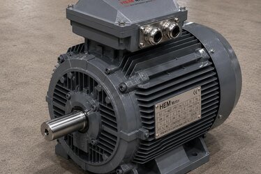
PE Conductor: The Motor's Protective Grounding
The PE (Protective Earth) conductor connects to the dedicated grounding terminal inside the motor's terminal box. Points to watch in this connection:
The Ground Terminal Inside the Terminal Box
Standard motors have a separate terminal marked with an earth symbol inside the terminal box. The PE conductor must always be connected to this terminal, with the correct cross-section and a firm tightening. It must not be confused with the phase conductors. The connection inside the terminal box should be considered together with the IP protection of the gland at the cable entry; we covered this in our motor terminal box and cable connection article.
Conductor Cross-Section and Tightening
The PE conductor's cross-section must comply with the phase conductors and the regulations; an inadequate cross-section can melt the conductor during a fault. The connection nut must be tightened to the appropriate torque and protected against loosening due to vibration.
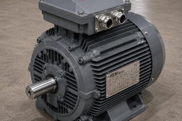
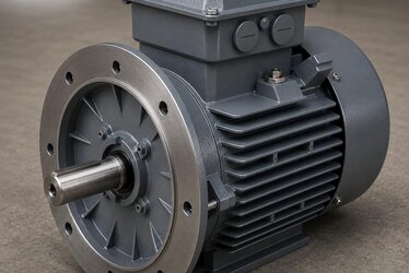
Body Ground Bolt: The Second Grounding Point
The vast majority of IE3 motors have, in addition to the terminal inside the terminal box, a body ground bolt on the outside of the motor body. This bolt is marked with an earth symbol and provides a second safety connection, especially in high-power motors and vibrating applications. The conductor connected to the external body ground bolt:
- Connects to the chassis, the machine body or the facility's equipotential busbar,
- Must be protected against rust and loosening, and must contact clean metal surface,
- Must not be allowed to form an insulating film due to paint or corrosion.
You can find detailed information on how grounding and electrical safety are achieved in cast iron body motors in our grounding and electrical safety in cast iron motors article.
Why Is Equipotential Bonding Needed?
Equipotential bonding brings all conductive metal parts in a facility (motor body, machine chassis, piping, metal structures) to the same potential. The aim is to prevent dangerous voltage differences forming between different metal surfaces. Its importance for the motor:
- No potential difference forms between the motor body and the machine it is attached to; touch risk decreases.
- In systems running with a frequency drive (VFD), high-frequency leakage currents find a safe path; this also reduces the bearing current problem.
- Electromagnetic compatibility (EMC) improves; nearby sensitive equipment is less affected.
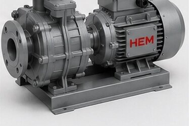
Especially in drive-fed applications, correct shielding of the cable between the motor and drive and correct equipotential bonding are critical for both safety and motor life. We covered the nuances of drive-fed use in our asynchronous motor with frequency drive (VFD) article.
Continuity of Grounding in Open-Field and Corrosive Environments
Once grounding is done correctly, it does not last forever; especially in open-field, seaside, chemical-plant and dusty-humid environments, grounding connections can deteriorate over time. Corrosion forms an insulating oxide/rust layer at the grounding point, slowly reducing conduction; this leaves the grounding inadequate during a fault. Therefore:
- Periodic inspection: Grounding connections should be on the maintenance schedule; loosening and corrosion should be checked regularly.
- Corrosion-resistant fasteners: Using suitably coated bolts and washers in the open field extends the connection's life.
- Protective grease or cover: Suitable protection after connection slows moisture and oxygen reaching the metal surface.
We covered corrosion protection in cast iron body motors operating in the open field in our corrosion protection and open-field use in cast iron motors article. Because it is invisible, grounding is the most neglected protection layer, yet the one most needed during a fault; periodic maintenance protects not the motor but the safety of people. For a periodic inspection schedule, our electric motor maintenance and periodic check schedule article offers a comprehensive plan.
Correct Supply: What to Check for Grounding?
When buying an IE3 motor, the following must be checked for grounding and safety:
- There must be a standards-compliant, marked ground terminal inside the terminal box,
- There must be an accessible body ground bolt on the outside of the body,
- The motor must be at least IP55 protection class and of a suitable insulation class,
- The efficiency class (IE3) must meet the application's regulatory requirement.
You can find which powers the IE3 efficiency class requirement applies to in our IE3 efficiency class mandate power table article, and the protective devices to request with the motor in our electric motor protection devices article. The right product group is IE3 efficient electric motors with 100% copper windings, class F insulation and IP55 protection. As a manufacturer and supplier, motors equipped with standards-compliant grounding points are supplied and technical support is provided.
The Protection Chain That Completes Grounding
Grounding does not work alone; it is part of a protection chain. When the links of this chain are set up correctly, the motor protects both people and itself:
Residual Current Device (RCD)
A residual current device detects the small leakage currents that pass to the body and cuts the circuit. But for it to work correctly, the motor body must be firmly grounded; without grounding, the device may not detect the fault in time. Grounding and residual current protection complement each other.
Thermal and Overcurrent Protection
Thermal relays and fuses protect the motor in overload and short-circuit conditions. When insulation fails and the body leaks to earth, a high fault current flows thanks to the low-resistance grounding path and the fuse trips quickly. We covered protective-device selection in our electric motor protection: thermal, relay and fuse selection article.
Winding Temperature Protection
PT100 and PTC thermistors monitor winding temperature and protect against overheating. This is a protection layer independent of grounding but complementary to it. You can find details in our motor winding temperature monitoring (PT100/PTC) article.
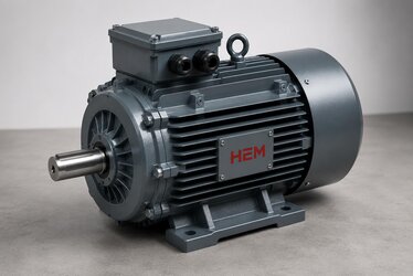
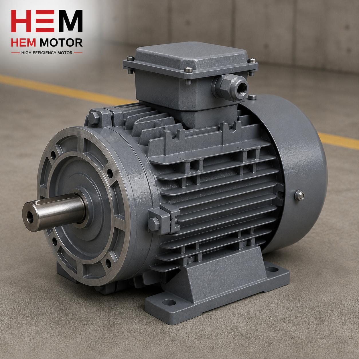
Grounding Difference Between Cast Iron and Aluminum Bodies
The motor's body material also affects the grounding practice. Safe grounding is possible with both body types, but the points to watch differ:
- Cast iron body: Provides high mechanical strength; the body ground bolt is usually larger and more firmly fixed. Preferred in vibrating and heavy-duty applications.
- Aluminum body: Light and compact; common in lower powers. Clearing the oxide layer from the connection surface is more critical for conductivity than with cast iron.
We compared the cast iron versus aluminum body question in terms of ambient conditions in our cast iron vs aluminum body motor selection article. In both cases the grounding surface must be clean, conductive and protected against corrosion.
The Most Common Grounding Mistakes in the Field
As a manufacturer and supplier, the grounding mistakes we see repeatedly in the field are:
- Connecting the PE conductor to a phase terminal: Confusing the ground terminal inside the terminal box; very dangerous.
- Grounding to a painted surface: Tightening the bolt over the paint prevents conduction.
- Insufficient cross-section conductor: A thin grounding cable can melt during a fault.
- Loose connection: A ground nut loosened by vibration eventually leaves the grounding broken.
- Neglecting one point: Connecting only the terminal-box terminal and leaving the body bolt empty, or vice versa.
These mistakes render the protection chain ineffective even if the motor is sound. For correct installation and nameplate matching, our exact matching with nameplate data before ordering article is also a useful complement.
Frequently Asked Questions
If the motor has both a terminal-box ground terminal and a body bolt, should I connect both?
Yes, both are designed for safety. The PE terminal inside the terminal box is the main connection point for the supply cable's protective conductor. The ground bolt on the outside of the body is used for connection to the facility's equipotential system and the chassis; it provides a second safety layer, especially in high-power and vibrating applications. Doing both correctly together is the safest solution.
The body is painted; can I connect the bolt over the paint?
No. Paint is an insulator and renders the grounding ineffective. The surface where the body ground bolt connects must be clean, conductive (unpainted) metal. The connection point must be cleared of paint, rust or corrosion, and properly protected against corrosion after connection. Otherwise the grounding "appears to exist" but does not actually conduct.
Does an IE3 motor running with a frequency drive need anything different for grounding?
Yes, high-frequency leakage currents arise in drive-fed systems. Therefore it is important to use a shielded cable between the motor and the drive, terminate the shield correctly at both ends, and have a sound equipotential bond. This reduces both EMC problems and early bearing failures due to bearing current. If drive-fed use is planned, it is advisable to state this to our sales team during motor selection.