English
 Türkçe
The IE5 synchronous reluctance motor delivers high efficiency even at part load, promising serious savings on the energy bill. However, this motor always runs with a variable frequency drive (VFD), and the drive's input stage distorts the current it draws from the grid, generating harmonics. If power quality on the grid (line) side is ignored, the efficiency advantage you gained in the motor can be given back through extra transformer losses, power-factor penalties, and the utility's power-quality enforcement. In this article we cover, in engineering terms but with a focus on the purchasing decision, how the 5th, 7th and 11th harmonics arise in an IE5 + drive combination, the concept of THD (Total Harmonic Distortion), the limits set by IEEE 519 and IEC 61000, and mitigation methods such as line reactors, 12-pulse rectifiers and active harmonic filters (AHF).
What Is a Harmonic and Why Does It Occur in an IE5 Drive?
On an ideal grid, current is a pure sine wave in phase with voltage. The diode bridge (6-pulse rectifier) at the input of the frequency drive charges the DC-bus capacitor only near the peaks of the voltage waveform. The result is that current is drawn from the grid in pulses. In Fourier analysis this pulsed current decomposes into components at integer multiples of the fundamental frequency (50 Hz). In a 6-pulse rectifier the dominant harmonics are the 5th (250 Hz), 7th (350 Hz), 11th (550 Hz) and 13th (650 Hz) orders. The general rule is h = 6k ± 1: 5, 7, 11, 13, 17, 19...
The IE5 synchronous reluctance motor itself does not generate harmonics; the harmonics come from the drive's input stage. So the harmonic issue is not unique to IE5 - it is common to all VFD-driven systems. But since the purpose of moving to IE5 is energy savings, ignoring harmonic-related extra losses directly extends the payback period of the project. For the motor-side sibling of this topic (output side, dV/dt, bearing currents) see our article on grounding and EMC in VFD systems.
Harmonic Orders and Typical Magnitudes
| Harmonic order (h) | Frequency (50 Hz base) | Typical magnitude in 6-pulse drive (unmitigated) | Sequence |
|---|---|---|---|
| 5 | 250 Hz | 25% - 40% | Negative |
| 7 | 350 Hz | 10% - 16% | Positive |
| 11 | 550 Hz | 6% - 9% | Negative |
| 13 | 650 Hz | 4% - 6% | Positive |
| 17 | 850 Hz | 2% - 4% | Negative |
| 19 | 950 Hz | 1% - 3% | Positive |
The magnitudes in the table are for a bare 6-pulse drive with no mitigation. The negative-sequence 5th harmonic is particularly notable because it tends to create a reverse-direction field in motors; when aggregated across a facility it causes extra heating in transformers and cables.
What Is THD? The Difference Between Current THD (THDi) and Voltage THD (THDv)
THD (Total Harmonic Distortion) is the ratio of the RMS value of all harmonic components to the fundamental component. There are two distinct THD concepts, and confusing them is a common mistake:
- THDi (Current THD): The distortion in the current the load draws from the grid. In a bare 6-pulse drive THDi can reach 35%-80%. It measures how much the drive "pollutes" the grid.
- THDv (Voltage THD): The voltage distortion created when this current flows through the source impedance (transformer + cable) of the grid. Other sensitive equipment in the facility is affected by this distorted voltage.
The key distinction: at the point of common coupling (PCC), THDv matters, because that is what affects neighbouring consumers. But the way to lower THDv is to lower THDi. The smaller (weaker) your transformer, the higher THDv the same THDi produces. That is why a harmonic assessment is always done together with the short-circuit power (Rsc).
What Are the IEEE 519 and IEC 61000 Limits?
Whether a harmonic level is "acceptable" is not arbitrary; it is defined by international standards. There are two main references:
IEEE 519-2014
IEEE 519 sets limits for both voltage and current distortion at the PCC. The current limits vary with the short-circuit ratio (Isc/IL). On a weak grid (low Isc/IL) the permitted TDD (Total Demand Distortion) is lower. For example, in systems below 1 kV:
| Isc/IL ratio | Permitted TDD (current) | Voltage THDv limit (≤1 kV) |
|---|---|---|
| < 20 | 5.0% | 8.0% |
| 20 - 50 | 8.0% | 8.0% |
| 50 - 100 | 12.0% | 8.0% |
| 100 - 1000 | 15.0% | 8.0% |
| > 1000 | 20.0% | 8.0% |
IEC 61000-3-2 / 3-12
The IEC side takes an equipment-based approach. IEC 61000-3-2 covers devices ≤16 A per phase; IEC 61000-3-12 defines the limit of each harmonic order as a percentage for devices between 16 A and 75 A. Industrial IE5 drives are generally evaluated under 61000-3-12 and, at the facility level, within the framework of IEEE 519 / IEC 61000-2-4 (compatibility levels). In practice the target is usually THDv ≤ 5%-8% at the PCC and keeping THDi within the TDD band the standard permits.
Why Do Harmonics Create Cost? Protecting the IE5 Efficiency Advantage
Harmonics are an "invisible" cost because they do not appear as a single line item on the bill. Yet they lose you money through these channels:
- Extra transformer and cable losses: Harmonic currents heat conductors more than the fundamental does, due to skin effect and eddy-current losses. This means the transformer must operate with derating (power reduction).
- Power factor and reactive penalty: Distortion lowers the true power factor. Since classic capacitor banks can resonate with harmonics, blind compensation can make the problem worse. To go deeper, our article on power factor and reactive power is useful.
- Neutral conductor overload: While the 3rd harmonic is usually not a problem in balanced three-phase systems, it accumulates in the neutral in facilities with a single-phase load mix.
- Sensitive equipment faults: Distorted voltage can cause instability in PLCs, instrument transformers and electronic boards.
The few points of efficiency you gain with an IE5 synchronous reluctance motor should not melt away through harmonic-related transformer/cable losses and possible power-quality penalties. That is why the right framing of an IE5 investment is to think holistically as "motor + drive + harmonic mitigation". We explained why the IE5 drive package is inseparable in our article on the IE5 drive package and cost.
Harmonic Mitigation Methods: Which Solution, When?
There is no single correct solution for harmonic mitigation; the approach is staged according to drive power, the facility's short-circuit power and the target THD level.
1. Line (Input) Reactor and DC-Bus Choke
This is the simplest and most cost-effective first step. An inductance connected in series at the drive input or on the DC bus lowers the peak of the current pulse and smooths the waveform. Typically a 3%-5% impedance line reactor reduces THDi from around 80% to the 35%-45% band. On its own it does not satisfy IEEE 519 in every scenario, but on small/medium drives and strong grids it is often sufficient. It also protects the drive against grid transient overvoltages.
2. Passive Harmonic Filter (Detuned/Tuned)
This is a reactor + capacitor combination tuned to specific harmonic orders (usually the 5th). It typically pulls THDi down to the 8%-12% band. Its cost is higher than a line reactor but lower than an AHF. It works well at constant load; if the load varies a lot its performance can drop.
3. 12-Pulse / 18-Pulse Rectifier
Using a phase-shifting transformer, the drive is fed by two supplies shifted by 30°. In a 12-pulse arrangement the 5th and 7th harmonics largely cancel each other; the dominant orders shift to the 11th and 13th. THDi typically drops to 8%-10%. It is economical at high powers (hundreds of kW) and especially in a single large drive, but it requires a phase-shifting transformer with its cost and footprint.
4. Active Harmonic Filter (AHF)
This is a power-electronics device that measures the distorted current drawn from the grid in real time and injects a compensating current exactly in anti-phase. It pulls THDi below 5%, often to around 3%. It works independently of load variation, can compensate several drives on the same bus from a single point, and can also handle reactive compensation if desired. It is the highest-performance but most expensive solution; it is preferred on critical grids and facilities subject to utility enforcement.
5. Active Front End (AFE) Drives
These are drives whose input stage is an IGBT active rectifier instead of a diode bridge. They inherently produce low THDi (usually <5%), provide unity power factor and offer regenerative capability (returning energy to the grid). In applications that aim to recover braking energy, this combines with the regenerative four-quadrant drive solution.
| Method | Typical THDi result | Relative cost | When suitable |
|---|---|---|---|
| Unmitigated 6-pulse | 35% - 80% | - | Not recommended |
| Line reactor (5%) | 35% - 45% | Low | Small/medium power, strong grid |
| Passive filter | 8% - 12% | Medium | Constant load, medium power |
| 12-pulse | 8% - 10% | Medium/High | Single large drive |
| AHF | < 5% (≈3%) | High | Multiple drives, critical grid |
| AFE drive | < 5% | High | Regenerative need |
What Information Is Needed to Choose the Right Mitigation?
To correctly size harmonic mitigation in an IE5 + drive project you need to gather: the supply transformer power and impedance of the facility (short-circuit power), the total drive power connected to the same bus, whether the load profile is constant or variable, whether the utility enforces THD limits, and the target THDv/THDi level. For correct installation and commissioning of the drive, our article on IE5 drive installation compatibility and commissioning is complementary.
Frequently Asked Questions
Does an IE5 motor produce more harmonics than other motors?
No. Harmonics are produced by the drive's input stage, not the motor. Because the IE5 synchronous reluctance motor cannot run without a drive, the harmonic topic is always on the agenda, but the harmonic level depends on the drive's input topology (6-pulse, 12-pulse, AFE) and the mitigation applied - not on the motor's efficiency class.
Is a line reactor alone enough to meet IEEE 519?
Often not on its own. A line reactor reduces THDi significantly, but unless you have a strong grid and low drive power it will not meet IEEE 519's current limits in every scenario. In facilities with enforcement, a passive filter, 12-pulse or AHF may be required. The right choice is determined by measuring the short-circuit power and the target THD.
Does harmonic mitigation increase or decrease energy savings?
Harmonic mitigation is primarily for power quality; it does not directly provide a large energy gain. However, reducing harmonics lowers extra transformer/cable losses and improves the power factor; this prevents the efficiency advantage gained with IE5 from melting away through penalties. In other words, harmonic mitigation "protects" the savings.
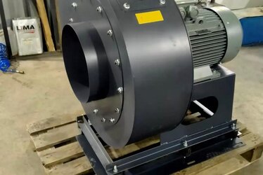
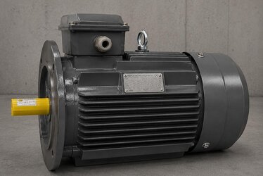
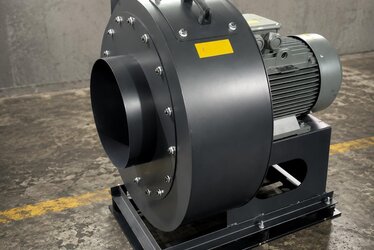
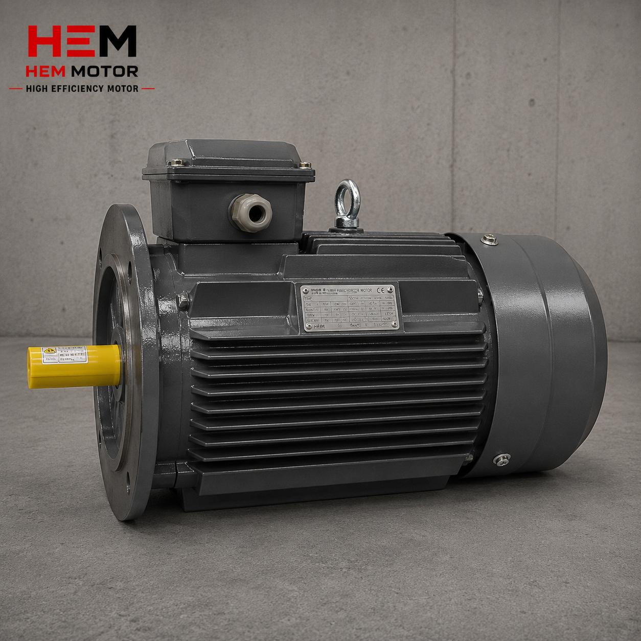
Contact Us for Stock and Fast Delivery
At HEM Motor we treat IE5 synchronous reluctance motors, compatible drives and grid-side power-quality solutions (line reactor, passive/active harmonic filter) as a holistic package. Based on your facility's transformer power, load profile and target THD level, we can determine the right mitigation together and protect your real energy savings without losing them to power-quality problems. To get a quote with manufacturer stock advantage and fast delivery, contact us and let us evaluate your project from an engineering standpoint.