English
 Türkçe

Whether a cast iron framed electric motor runs vibration-free, quietly and for a long service life in the field depends not only on its electrical design but also on an invisible mechanical detail: the machining quality of the foot mounting surfaces. If the surfaces where the four feet sit on the floor or base are not machined precisely enough for parallelism and flatness (coplanarity), the frame is stressed when the motor is bolted down. This condition, called "soft foot", is a hidden source of a chain of problems ranging from vibration to bearing damage. In this article we discuss why foot machining tolerances matter so much, how soft foot occurs, how it is checked and corrected in the field, and how to recognize quality casting and machining when purchasing.
The Foot Mounting Surface: The Critical Interface Where the Motor Meets the Floor
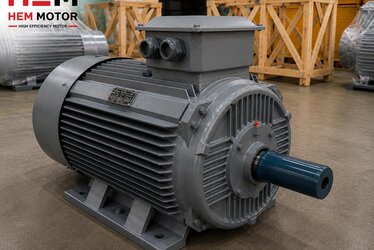
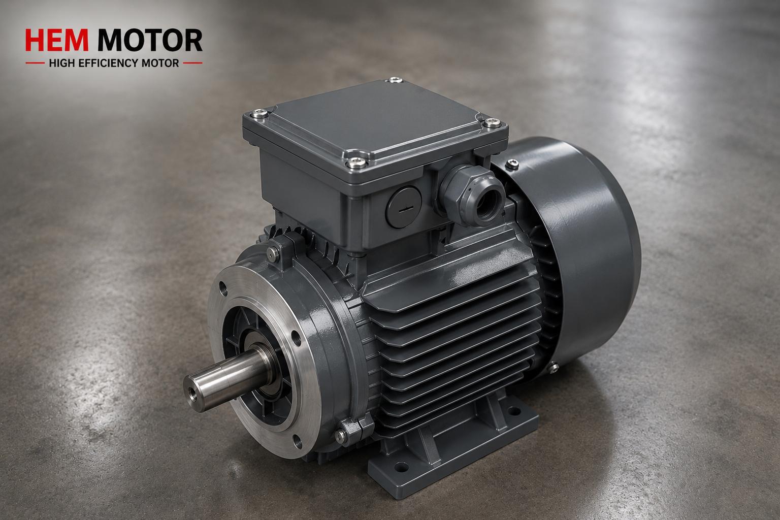
A cast iron frame is preferred in heavy-duty applications for its high mechanical strength and rigidity. But for this rigid frame to deliver its advantage in the field, the feet must sit fully and free of stress on the base. The bottom surfaces of the four feet should ideally be in the same plane (coplanar) and parallel to one another. After casting, these surfaces are machined (milling/grinding) and kept within a defined parallelism/flatness tolerance.
Why does this tolerance matter? Because the motor is connected to a driven machine via a coupling or belt-and-pulley. If the feet do not sit properly, the motor's shaft axis shifts out of alignment; this leads to coupling/pulley misalignment, additional vibration and premature wear. In other words, foot machining quality is directly the foundation of shaft alignment and therefore of the entire drive train's life.
What Do Parallelism and Flatness (Coplanarity) Mean?
Flatness describes how close the four foot surfaces are to a single ideal plane. If one foot stands higher or lower than the others, flatness is degraded. Parallelism means that this seating plane is at the correct angle (parallel) relative to the motor's shaft axis. In a good motor these two measures, combined with frame rigidity, allow the motor to sit free of stress and without deforming when bolted down.
What Is Soft Foot and How Does It Occur?
Soft foot is the condition where one or more of the motor's feet do not make full contact with the base. Just like a table with one short leg; when you tighten the bolt, the frame bends to close the gap. This bending creates continuous mechanical stress in the frame and bearings. There are two basic types:
- Parallel soft foot: There is a uniform but different-height gap under one foot compared to the others. It usually arises from an uneven floor or unequal foot heights.
- Angular soft foot: The foot surface is not parallel to the base; only one edge touches while a wedge-shaped opening remains at the other edge. This stems from the foot machining angle or a sloped floor.
When the bolt is tightened, the frame is forced to close these gaps. The result: frame distortion, shaft-axis shift, increased vibration and additional load on the bearings.
The Damage Caused by Soft Foot: From Vibration to Bearing Failure
Foot stress produces consequences far more serious than they appear:
- Increased vibration: Frame distortion disturbs the balance of the rotating rotor and the air gap, raising the vibration level. High vibration is both a measurable loss of quality and a warning of further cascading failures.
- Shortened bearing life: The additional static load on the bearings stresses the bearing seat and significantly shortens bearing life. The root cause of many premature bearing failures is in fact an uncorrected soft foot.
- Air-gap distortion: Frame bending can make the air gap between stator and rotor uneven; this means magnetic imbalance and additional heating.
- Loss of alignment: Coupling alignment performed without removing soft foot does not last; the alignment is disturbed again every time the motor is loosened and retightened.
If you want to look deeper into vibration and bearings, our articles on bearing and bearing life in cast iron motors and impact strength and frame rigidity complete the topic.
Field Soft Foot Check and Correction (Shim/Adjustment)
The good news: soft foot is a defect that can be measured and corrected with the right method. The classic approach applied during installation is:
- Measurement with a dial indicator: With all bolts tightened, a dial indicator is placed to track the foot's movement. Each foot bolt is loosened in turn and the amount the foot rises (the gap) is read. A rise above the defined limit is a sign of soft foot.
- Identifying the gap: The gap under the foot can also be measured directly with a feeler gauge; this reveals whether it is angular or parallel.
- Correction with shims (adjustment plates): The detected gap is filled with stainless steel shim plates of suitable thickness. Angular soft foot may require stepped/graduated shims. The goal is to let all feet sit free of stress without forcing the frame.
- Verification: After shimming, the measurement is repeated; the process continues until the remaining gap falls below the acceptance limit. Only then is precise coupling alignment performed.
This process is an inseparable part of mounting quality. For correct bolt, nut and floor/base mounting see our bolt-nut and base mounting guide, and for coupling selection and shaft alignment our flexible/rigid coupling and alignment article.
Signs of Quality Casting and Machining When Purchasing
The way to minimize soft foot risk is to buy a rigid frame with properly machined foot surfaces from the start. When purchasing, you can recognize quality cast iron and machining from these signs:
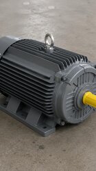
- Clean, properly machined foot surfaces: The bottom surfaces of the feet should look smooth, marked by machining, and in the same plane. Feet left as raw cast surfaces increase soft foot risk.
- Frame rigidity and rib structure: A well-designed cast iron frame is supported by ribs; this increases both rigidity and heat dissipation. We covered the subject in our rib design article.
- Casting material quality: Casting grades such as EN-GJL (GG20/GG25) and a homogeneous, pore-free casting preserve the integrity of the foot surface after machining. For detail see our EN-GJL grade difference and casting quality and porosity articles.
- General machining and concentricity tolerances: Precise machining of the flange, shaft and bearing seats too is a holistic indicator of the manufacturer's machining quality. Our machining, tolerance and concentricity article focuses on this subject.
To see when a cast iron frame should be preferred over aluminum and how to select foot height (H dimension), our cast iron vs aluminum and foot height and axial alignment articles are useful. For the full product range you can visit the HEM Motor home page.
Pre- and Post-Mounting Check
Even a well-machined motor can experience soft foot if it is poorly mounted on a poor floor. Therefore the floor/base must also be flat and rigid. When the motor is received, the foot surfaces should be checked to be undamaged and clean; a soft foot measurement must absolutely be performed during installation. This check is one of the fundamental steps to be done before commissioning and prevents many future vibration/bearing problems from the start.
Frequently Asked Questions
Does soft foot occur in every motor, or is it a sign of poor quality?
Soft foot comes from two sources: the foot machining quality of the motor and the flatness of the floor/base. A rigid cast iron frame with well-machined feet greatly reduces soft foot risk; but it can still occur if the floor is sloped. Therefore you need both to buy a quality motor and to measure and correct with shims during installation. So soft foot relates to both product and mounting quality.
Does foot surface parallelism really affect vibration that much?
Yes. When the feet sit under stress, the frame bends, the shaft axis shifts and the air gap is disturbed. All of these directly raise the vibration level. The root cause of many "unexplained" high-vibration cases is an uncorrected soft foot and the resulting misalignment. For this reason soft foot must absolutely be removed before precise alignment.
Is correcting soft foot with shims enough, or what else should I do?
After stress-free seating is achieved with shims, precise coupling/pulley alignment must be performed. In addition, it is important to tighten the bolts evenly to the correct torque, keep the floor rigid and re-measure foot seating during periodic checks. Soft foot should not be treated as a one-time matter but as part of mounting quality.
Get a Quote
For cast iron framed motors with precisely machined foot surfaces that run rigidly and vibration-free, consult the HEM Motor expert team. Share your power, speed, frame size, mounting type and application; let us determine the most suitable motor together. To get a quote right away, call +90 (532) 345 49 86 or reach us via our contact page.
Purchasing and Mounting Checklist
- Check that the bottom surfaces of the motor feet are properly machined and in the same plane.
- Evaluate that frame rigidity and rib structure suit the application.
- Ask about the casting grade (EN-GJL/GG20/GG25) and casting quality (pore-free).
- Make sure the floor/base is flat and rigid.
- Perform a soft foot measurement with a dial indicator or feeler gauge during installation.
- Eliminate the detected gap with suitable shim plates and verify the measurement.
- Move to precise coupling/pulley alignment only after soft foot is removed.
- Tighten the bolts to the correct and even torque; recheck foot seating during periodic maintenance.