English
 Türkçe
One of the most insidious mistakes made when mounting an electric motor to the floor or to a machine is soft foot. At first glance the motor seems to sit firmly; all four feet touch the floor. But if one or more of the feet are not exactly in the same plane, the body twists slightly the moment you tighten the bolts. This invisible distortion disrupts the air gap between stator and rotor inside the motor, strains the bearings, increases vibration and over time leads to early bearing damage or winding problems. In this article we treat soft foot, foot flatness and shaft runout (TIR) as a matter of mounting quality; we explain how these faults arise, how they are detected, how they are corrected with laser alignment and shims, the acceptance limits, and the correct mounting-and-inspection method, all with technical tables.
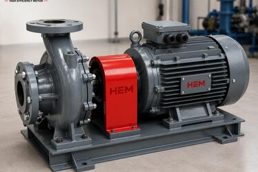
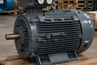
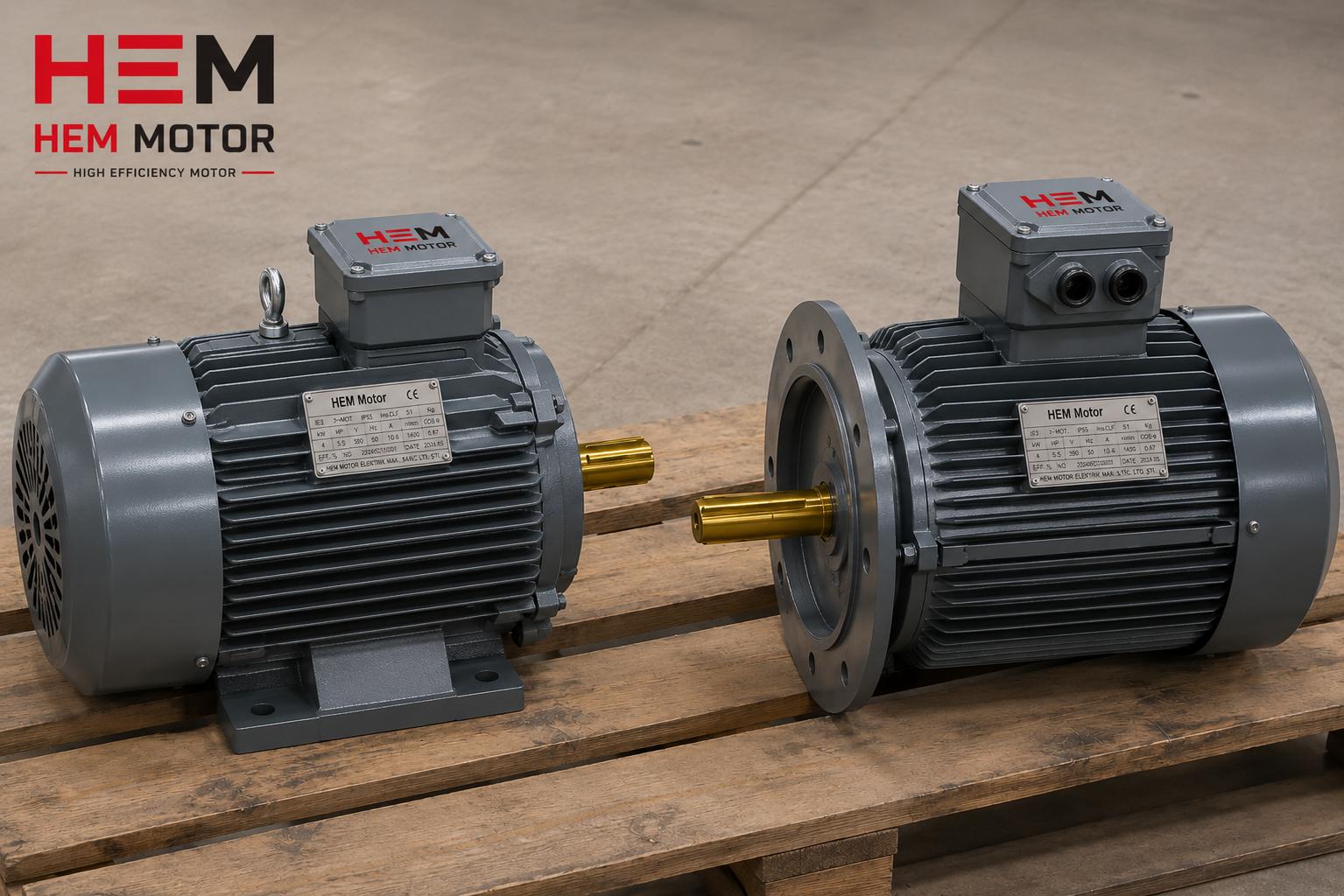
Soft foot and misalignment are often the real source of vibration and heating problems that get labeled as "motor faulty"; yet the motor itself may be flawless. Correct mounting determines the lifetime of even the highest-quality motor. At HEM Motor we supply cast iron and premium-efficiency motors with precisely machined feet and flatness-checked bodies; this article is a guide to obtaining full performance from these motors by performing correct mounting and inspection in the field.
What Is Soft Foot?
Soft foot is the condition where the motor's body twists when the bolts are tightened, because the four mounting feet are not in the same plane or the surface they sit on is not flat. There are two main types:
- Parallel soft foot: One foot stays higher than the others; there is a clear gap between the foot and the floor. When the bolt is tightened, the body is pulled down at that corner and twists.
- Angular soft foot: The foot does not sit exactly parallel to the floor but at an angle; only one edge touches. When the bolt is tightened, the foot is forced to flatten and the body is strained.
In both cases the result is the same: the body is mechanically strained, the stator housing deforms slightly, and this deformation transfers to the bearing seats and the air gap. Soft foot is usually not visible to the eye; but it is clearly revealed when measured with a dial indicator or a laser alignment device.
Measuring and Correcting Soft Foot
The classic method to detect soft foot is to loosen each foot's bolt one by one and measure with a dial indicator how much the body lifts at that corner. If the body clearly springs up when the bolt is loosened, there is soft foot at that foot. Modern laser alignment devices perform this measurement in an automatic "soft foot" mode and directly show how much correction is needed at which foot.
The correction is made by placing a stainless-steel shim of suitable thickness between the foot and the floor. Shims are chosen to completely fill the gap between foot and floor; the goal is to let all four feet rest on the floor without strain. There are a few points to watch in shim selection:
- Use as few shims as possible; a multi-layer stack of shims flexes and can recreate soft foot.
- Shims must be clean, smooth and stainless; a dirty or dented shim does not give a correct measurement.
- The shim must cover the entire contact surface of the foot; a small or wrongly positioned shim creates point loading.
| Check/Parameter | Typical Acceptance Limit | Effect |
|---|---|---|
| Soft foot | ≤ 0.05 mm | Body twist, air-gap distortion |
| Parallel misalignment (offset) | ~0.05-0.10 mm | Bearing load, vibration |
| Angular misalignment | ~0.05-0.08 mm/100 mm | Coupling strain, heating |
| Shaft runout (radial TIR) | ~0.03-0.05 mm | Rotational imbalance, vibration |
| Shaft-end axial runout | ~0.02-0.04 mm | Coupling and axial load |
These values are general acceptance ranges; on critical and high-speed applications the limits are tighter, while on low-speed coarse applications they may be a little looser. What matters is correcting soft foot before alignment, because an alignment done on a twisted body is disturbed when the bolt is loosened and re-tightened.
Why Does Misalignment Cost So Much?
Soft foot and misalignment look like small fractions of a millimeter at first glance; but these small deviations turn into large costs over the motor's lifetime. The consequences of misalignment fall under three main headings, all feeding each other: increased vibration, bearing load and energy loss. When the motor and driven-machine shafts do not rotate on exactly the same axis, the coupling is forced to flex on every turn; this flexing both produces heat and strains the bearings. As a result the bearings fail well before their design life and the motor appears to give a "causeless" fault.
Vibration is the most visible symptom of misalignment and often shows itself at 1x or 2x rotational frequency. High vibration fatigues not only the bearings but also the winding, the terminal connections and even the body bolts; bolts that loosen over time start a new misalignment cycle. Moreover, in a misaligned system, coupling friction and bearing load increase the power the motor draws; that is, misalignment is reflected directly in the energy bill. Investing in an efficient motor and then mounting it misaligned means spending part of the savings gained on friction and vibration.
The insidious part is that this damage progresses slowly. After mounting the motor appears to run without trouble for months; but the bearings quietly wear, the grease degrades, and one day the problem surfaces with a sudden bearing failure or a rising vibration alarm. At that point you must account not only for the motor but often for the driven machine and the production loss too. That is why correct mounting is not a "nice to have" detail but a fundamental step that directly determines operating cost.
What Is Shaft Runout (TIR)?
Shaft runout is the measure of how much the shaft surface or the coupling surface deviates from the ideal axis of rotation while the motor shaft is turned. It is called TIR (Total Indicator Reading) or runout, and is measured by touching a dial indicator to the shaft surface and turning the shaft one full revolution; the difference between the maximum and minimum reading on the indicator is the total runout. There are two kinds of runout:
- Radial runout: The lateral deviation of the shaft surface from the axis of rotation; a bent or off-center shaft produces vibration.
- Axial runout: The back-and-forth play of the shaft end or the coupling surface along the axis of rotation; it creates strain in the coupling.
If shaft runout exceeds the acceptance limit, it transmits vibration and variable load to the machine it is coupled to; this fatigues both the motor bearings and the bearings of the driven machine. Runout can come from the motor's own manufacturing quality (shaft machining tolerance) or from a wrongly fitted coupling or pulley. That is why shaft and coupling runout should be checked together during mounting.
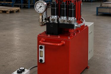
Laser Alignment: The Modern Method
Traditional alignment methods (straightedge, dial-indicator bracket) require experience and have a high margin of error. Laser alignment devices use a laser beam between two sensors mounted on the motor and driven-machine shafts to measure parallel and angular misalignment with micron precision, and directly tell you how much shim to add to which foot or in which direction and by how much to move the motor. This both saves time and provides a repeatable, documentable alignment. On critical machines, laser alignment has now become a standard.
The Alignment Difference in Coupled vs. Belt-Pulley Drive
The alignment method changes according to how the motor transmits load. There are two basic cases: direct coupled drive and belt-pulley drive. In both, soft foot must be eliminated, but the alignment logic differs.
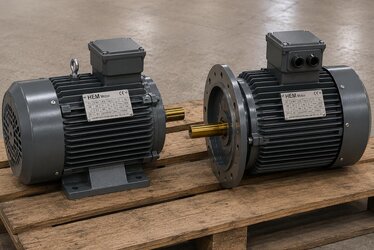
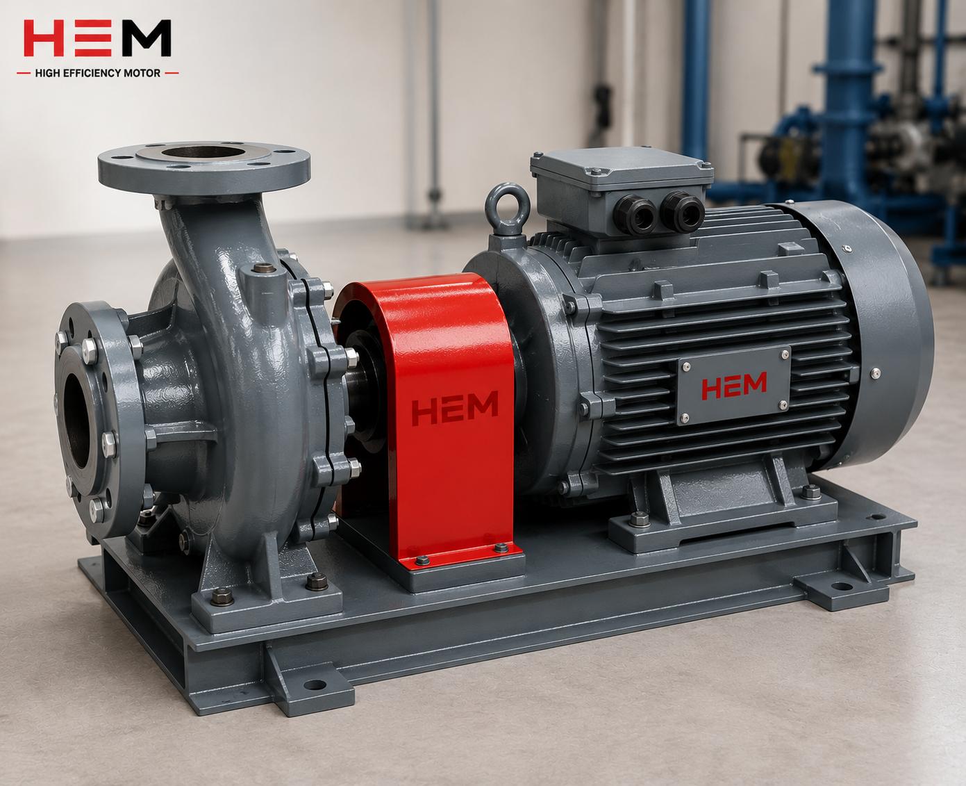
- Coupled drive: The motor shaft and the driven-machine shaft must be on the same axis. Here parallel (offset) and angular alignment are measured; the coupling type (flexible or rigid) sets the acceptance limit. Rigid couplings tolerate no misalignment at all, while flexible couplings absorb some deviation, but this is not a reason to neglect alignment.
- Belt-pulley drive: Here it is important that the two pulleys are in the same plane (pulley alignment) and that the belt is at the correct tension. A skewed pulley alignment causes the belt to wear on one edge and shortens bearing life due to side load.
In both drive types, adding shims under the motor's feet, sliding the motor in the horizontal plane and rotating it when necessary are the tools of alignment. The choice of flexible or rigid coupling also directly affects the alignment tolerance; that is why coupling type and alignment acceptance limit should be considered together when planning the mounting. In belt-pulley systems, belt tension additionally determines both transmission efficiency and bearing side load; an over-tight belt fatigues the bearings, while a loose belt creates slip and efficiency loss.
The Correct Mounting and Inspection Sequence
A correct mounting follows a particular sequence; when this sequence is skipped, it becomes hard to find the source of problems that appear later. The recommended sequence is:
- 1. Foundation/base check: The foundation must be flat, solid and free of resonance; a loose or vibrating base spoils everything.
- 2. Rough placement and bolting: The motor is set in place, bolts are fitted by hand but not fully tightened.
- 3. Soft foot check: Each foot is checked one by one and the necessary shims are added.
- 4. Alignment: After soft foot is eliminated, parallel and angular alignment (preferably with a laser) is performed.
- 5. Tightening to torque: The bolts are tightened to the proper anchor torque in a cross sequence.
- 6. Final check: Alignment is re-verified after tightening and confirmed by vibration measurement.
The most critical point of this sequence is eliminating soft foot before alignment. Even the most precise alignment done on a twisted body changes when the bolt is loosened and tightened. Moreover, tightening the bolts to the correct anchor torque and in a cross sequence loads the body evenly and prevents a new distortion from arising.
Frequently Asked Questions
Isn't soft foot a small error, is it really important?
Though it looks small, its effect is large. Even a 0.1 mm soft foot can twist the body enough to disrupt the air gap, increase bearing load and raise vibration. Moreover, its effect is hidden; while the motor appears to "run," the bearings quietly wear and a few months later it appears as an early fault. That is why soft foot is a step of mounting that must not be skipped.
Can a good alignment be done without laser alignment?
An experienced technician can get good results with traditional methods (dial-indicator bracket, straightedge); but laser alignment is faster, more precise and more repeatable. Especially on high-speed and critical machines, the micron precision and documentability that laser alignment provides easily justify the investment. On low-speed coarse applications, the traditional method may suffice.
If shaft runout is high, is the motor faulty?
Not always. High runout can come from the motor's own shaft machining tolerance, or from a wrongly fitted coupling, a bent pulley or a wrong fit tolerance. That is why measuring runout first on the bare shaft without the coupling/pulley fitted, and then with the coupling, helps to separate whether the problem comes from the motor or from the mounting.
Correct mounting and inspection are critical for obtaining full lifetime and low vibration from your motors. Request a quote with fast delivery from HEM Motor stock for motors with precisely machined feet, checked flatness and shaft tolerance conforming to quality criteria; with the correct mounting sequence and acceptance limits, keep your motor running healthily from the first day. Remember: even the best motor wears out early with wrong mounting; correct mounting is the invisible insurance of your investment.