English
 Türkçe
When an induction motor must be placed far from its supply, the cable length is a parameter often overlooked yet it causes two separate, serious problems. The first, in grid-fed systems, is the voltage drop along the cable: the voltage reaching the motor terminal falls below the rated value due to the loss along the line, and the motor runs with insufficient torque, excess current and heating. The second appears in systems fed by a variable frequency drive (VFD): the reflected wave and dV/dt voltage spike. The fast-switched pulses of the drive create peak voltages at the motor terminal on a long cable that rise to nearly twice the DC-bus voltage, wearing out the winding insulation. At HEM Motor, this article explains both faces of long cable distance, cable cross-section selection, the use of dV/dt and sine filters, cable length limits and correct motor-drive selection from an engineering perspective.
Problem 1: Voltage Drop in the Cable and Cross-Section Selection
Every conductor has resistance; when current flows through that resistance, a voltage drop forms along the cable. The longer the cable and the smaller the cross-section, the more the voltage reaching the motor terminal falls. When the motor is fed at low voltage, its torque capacity drops (torque is proportional to the square of the voltage), it draws more current to deliver the same power, and that means extra heating and efficiency loss. Especially at the moment of starting, when the current is high, on long and thin cables the motor may struggle to start.
In standard practice, the voltage drop at the motor terminal is targeted not to exceed 3-5 percent of the rated value. The cable cross-section is chosen according to current, distance and the allowed voltage drop. The table below shows the approximate distance-cross-section relationship for a typical motor current; exact values are calculated from current, power factor and cable type.
| Cable Distance | Undersize Risk | Recommended Approach | Voltage Drop Target |
|---|---|---|---|
| 0 - 50 m | Low | Standard cross-section is enough | < 2% |
| 50 - 150 m | Medium | Consider one size larger | < 3% |
| 150 - 300 m | High | Increase cross-section, calculation required | < 4% |
| 300 m and above | Very high | Increase cross-section + review supply point | < 5% |
- You may need to increase the cable cross-section based on the voltage-drop target, not just the current.
- Because the starting current is high, the drop at the moment of start must also be checked.
- On long lines, parallel cables or moving the supply point closer to the motor are evaluated.
- The earth conductor cross-section must also be chosen correctly for short-circuit protection.
Problem 2: Reflected Wave and dV/dt Voltage Spike on a VFD
A variable frequency drive applies to the motor not a sine wave but very fast-rising and falling voltage pulses (PWM). The rise rate (dV/dt) of these pulses is very high. The cable behaves electrically like a transmission line; as the pulse travels from the drive to the motor, it reflects at the motor terminal due to the impedance mismatch. When the reflected wave superimposes on the incoming wave, peak voltages reaching nearly twice the DC-bus voltage form at the motor terminal. This effect becomes more pronounced as the cable lengthens, because the pulse has time to reach its full peak before reflecting back from the motor terminal.
These high peak voltages fall disproportionately on the motor's first winding turns and gradually degrade the winding insulation; the result is an early winding fault (turn-to-turn fault). The risk grows as cable length, switching frequency and the drive's pulse rise rate increase. The table below summarizes the approximate risk level by cable length and the recommended measure.
| Cable Length (VFD-Motor) | Reflected Wave Risk | Terminal Peak Voltage | Recommended Measure |
|---|---|---|---|
| 0 - 15 m | Low | ~1.2-1.4 × Udc | Usually no measure needed |
| 15 - 50 m | Medium | ~1.6-1.8 × Udc | dV/dt filter / motor reactor |
| 50 - 100 m | High | ~1.8-2.0 × Udc | dV/dt filter mandatory |
| 100 m and above | Very high | ~2.0 × Udc and above | Sine filter recommended |
Solution: dV/dt Filter, Motor Reactor and Sine Filter
There are three main solutions against the reflected wave and dV/dt voltage spike. Which one is chosen depends on cable length, switching frequency and the motor's insulation strength:
- Motor (output) reactor: Slows the pulse rise rate and provides economical protection at medium distances.
- dV/dt filter: Made of a reactor and capacitor; limits the peak value and rise rate of the pulse. It is the standard solution on long cables.
- Sine filter: Converts the drive output almost to a sine wave; used on very long cables and in applications most sensitive to voltage spikes, it is the most comprehensive protection.
Besides the filter, the second important line of defense is the motor itself: in a motor meant to run on a drive, the inverter-duty (reinforced insulation) winding is designed to withstand these voltage spikes. When a long cable and a VFD come together, the combination of both a filter and an inverter-duty winding is the safest approach.
Critical Cable Length and the Pulse Rise Time Relationship
The fundamental quantity that determines whether the reflected wave reaches its full peak at the motor terminal is the comparison between the pulse rise time and the pulse travel time along the cable. If the cable is long enough that the reflection cannot return while the pulse is still rising, the peak voltage at the terminal climbs to nearly double. This threshold is called the critical cable length. Because the switching elements (IGBT) of modern drives are very fast, the pulse rise time has shortened, so the critical cable length has shortened too; this means measures may now be needed even over short distances.
In practice three variables set this limit: the pulse rise time (drive type), the cable type and length, and the motor terminal impedance. The shorter the rise time, the shorter the critical cable length. Therefore the filter must be chosen not only by meters but also by the drive's switching characteristic. The maximum filterless cable length given by the drive manufacturer should be the starting point of the design.
- With fast-IGBT drives the critical cable length shortens; a spike can form even at short distances.
- Cable type (capacitance) and winding structure affect the reflection behavior.
- Filter selection is made by evaluating meters + drive switching speed + motor insulation class together.
- In systems where multiple motors are connected to one drive, the total cable length is considered.
Practical Consequences and Symptoms of Voltage Drop
When there is excessive voltage drop in the cable, the motor shows it through various symptoms. Recognizing these symptoms enables quick field diagnosis. The most common signs are: the motor starting slowly and with difficulty, frequently tripping overcurrent protection at full load, heating more than normal, the speed dropping under load due to insufficient torque, and efficiency loss. These symptoms are often interpreted as a motor fault; yet the root cause is an inadequate cable cross-section.
So when a problem occurs on a long-line motor, the first thing to check is the actual voltage at the motor terminal. If the voltage measured at the terminal is significantly below the rated value, the solution is not to replace the motor but to increase the cable cross-section or rearrange the supply point. On a correctly designed line none of these problems appear, which shows why choosing the right cross-section from the start is important.
Grounding, EMC and Shielded Cable
In long-cable VFD systems the problem is not only the voltage spike; fast switching also creates leakage capacitive currents and electromagnetic interference (EMC). Therefore a shielded cable should be used between motor and drive, the shield terminated 360 degrees at both ends, and the motor grounded correctly. Incorrect grounding can lead to bearing current and bearing damage. A shaft grounding brush or an insulated bearing provides protection, especially in high-power, long-cable applications.
- Shielded cable between VFD and motor, with 360° shield termination.
- Motor and drive grounds at the same potential, short and low-impedance.
- Against bearing-current risk, a shaft grounding brush or insulated bearing.
- Route power and control cables separately, avoiding long parallel runs.
Applications Where Long Cable Is Common
Long cable distance is almost unavoidable in certain applications, and both problems described above are frequent in them. Recognizing these applications makes it easier to design the measures from the start:
- Deep-well and submersible pumps: The motor is underground and the drive at the surface, so the cable is tens to hundreds of meters; both voltage drop and dV/dt spike are critical.
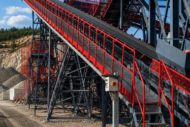
- Mine and quarry sites: Long, open-area cable routes between panel and motor; cross-section and filter are planned together.
- Water treatment and pumping stations: Pumps are distributed and the central panel is far.
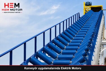
- Port and long conveyor lines: Drive motors are spread along the line, with large cable distances.
- Cooling tower and roof fans: Drive indoors, motor far away; shielded cable and filter are standard.
The common mistake in these applications is not accounting for the cable distance at the project stage and running into the problem after the motor is commissioned. The right approach is to treat the distance as a design input from the very start and to size the motor, cable, filter and grounding together.
Insulation Class and Winding Selection on the Motor Side
If the filter is the outer line of defense, the motor's winding insulation is the inner line. A standard motor winding wears out over time when continuously exposed to high dV/dt pulses. Windings with inverter-duty or reinforced insulation are designed to withstand higher peak voltages and steeper pulses; the turn-to-turn insulation is strengthened and the phase-phase and phase-ground withstand is increased. When selecting a motor for a long-cable, high-switching-frequency system, this feature must always be queried.
- Inverter-duty winding withstands high peak voltage and steep pulses; recommended on long cables.
- Insulation class (F/H) and temperature margin must cover the extra heating in drive operation.
- Using a filter together with an inverter-duty winding is the safest combination.
- PTC/PT100 thermal sensors should be requested as standard for winding protection.
Correct Motor and Cable Selection: Think Together
The long-cable problem is solved by treating the motor and cable not separately but as a system. In a grid-fed system the priority is the cable cross-section; the voltage drop is calculated and the cross-section increased accordingly. In a VFD system the priority is the voltage spike; the filter is chosen by cable length and the motor has an inverter-duty winding. In both cases, correct grounding and EMC connection determine the reliability of the system. HEM Motor stocks a wide range of IE3 and higher-efficiency motors with inverter-duty winding options, suited to long-cable and VFD applications.
Frequently Asked Questions
What is the maximum cable length between a VFD and a motor?
There is no single fixed limit; it depends on the drive type, switching frequency and filter use. In filterless systems, measures are usually needed above 15-50 meters. With a dV/dt filter you can safely reach hundreds of meters, and with a sine filter even longer distances. The drive manufacturer's cable length limit must always be considered.
Does increasing the cable cross-section solve the reflected-wave problem?
No. Increasing the cross-section reduces the voltage drop but does not solve the reflected wave and dV/dt spike; in some cases it can even increase the capacitive effect. The correct solution for the reflected wave is a filter and an inverter-duty winding. Since the two problems are different, they must be addressed separately.
Is an inverter-duty winding always necessary?
In short-cable, low-voltage applications a standard winding may be enough. But where a long cable, high voltage and high switching frequency are involved, an inverter-duty winding is strongly recommended; it markedly increases winding life and reliability.
Conclusion and Supply
Long cable distance creates two different problems: voltage drop in a grid-fed system, and reflected wave and dV/dt voltage spike in a VFD system. With the right cable cross-section, the right filter, an inverter-duty winding and correct grounding, these problems are brought under control and the motor's life is preserved. At HEM Motor we offer motors with inverter-duty winding options, fast delivery from manufacturer stock and application-specific technical support for your long-cable and VFD applications. Reach us with your cable distance, drive type and power details; let us choose the right motor and protection combination together and prepare a tailored quote for you.
Related guides: Inverter-Duty Winding and dU/dt Filter Selection, Grounding, EMC and VFD Connection, VFD Harmonic Heating and Bearing Current, Rated Current, Cable, Fuse and Contactor and Cable Connection and Lug Selection.