English
 Türkçe
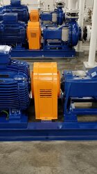
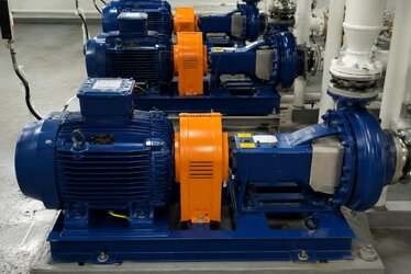
In water supply, cooling towers, fire mains and process feed systems, connecting several pumps in parallel rather than using one large pump is a common engineering choice. Parallel pumps respond flexibly to variable flow demand, provide redundancy and save energy at part load. The price of that flexibility is that motor selection must be done far more carefully than in a single-pump system. Without correctly understanding how pump curves add up, how motors stage in and out as flow drops, each pump's minimum continuous flow limit, and rotating duty for even wear, you will size the motor wrong and cause overheating and premature failure. This article covers motor selection for parallel pumps together with flow sharing, operating-point shift and protection logic, stepping through the single-versus-multiple-motor question, speed and mounting selection, and commissioning notes.
Parallel Pump Curve: Flows Add, Head Stays the Same
The basic rule of parallel operation is simple: two identical pumps on the same suction and discharge manifold add their flows at a given head (H). At the common operating pressure the system flow approaches twice that of a single pump. Head does not add; both pumps produce the same H. The intersection of the system curve (pipe friction + static lift) with the combined pump curve gives the real operating point. Selecting motor power without seeing this intersection on a graph is guesswork.
The critical point: if the system curve is steep (high friction loss), adding a second pump does not increase flow as much as expected; instead of doubling you may gain only 30-40 percent. This is because pipe friction grows with the square of flow. In that case each pump shifts to the left (lower flow) from its single-running point. A leftward shift looks good for the motor, but it risks pushing the pump below its minimum continuous flow. Conversely, if the system curve is flat (static-head dominated, low friction), the gain from parallel operation is high and flow really does approach double; such lines are ideal for parallel pumping.
The shape of the system curve also determines how many pumps add meaningful flow. On a very steep system, adding a fourth or fifth pump brings almost no extra flow; it only pushes the pumps toward minimum flow. So the number of pumps in the parallel pool must be limited to the "efficient parallel window" the system curve allows.
Operating-Point Shift and Motor Load
With a single pump running, the pump operates on the right of its curve, at high flow, and draws power close to motor rated output. When the second pump starts, both shift left and the power drawn per pump drops. Therefore in a parallel system the most critical load case is often the moment a single pump runs alone: it runs out to the far right of its curve and the motor draws maximum power. Motor selection must be based on this "one pump, highest flow" scenario; otherwise, at night under low demand with a single pump running, the motor is continuously overloaded.
In centrifugal pumps the power curve rises with flow (rising power characteristic). The further the pump shifts right, the higher the kW it draws. Many failures arise because the engineer sized the motor only for the "design point" and ignored the moment the pump runs furthest right in real operation (especially high flow at low pressure). The correct path is to size the motor to cover the maximum power draw across the pump's full operating range, with a reasonable safety margin.
Minimum Continuous Flow Protection
Every centrifugal pump has a minimum continuous flow limit. Below this, water churning inside the impeller heats up, the liquid risks vaporizing, axial thrust becomes unbalanced and vibration rises. In a parallel system, when flow is low and several pumps are still running, the flow per pump can fall below the minimum. That is why staging logic in a parallel system is mandatory not only for energy but for pump protection: as flow drops the number of pumps must be reduced, and if the last pump still falls below minimum, a minimum-flow recirculation line (automatic recirculation valve or orifice bypass) must come into play.
If minimum-flow protection is neglected, one of the costliest outcomes occurs: water vaporizes inside the pump, the impeller runs dry, and seals and bearings are damaged within seconds. On the motor side, even though power falls at low flow the motor does not stop; the real damage is mechanical and often the whole pump-motor set is taken out of service. So staging thresholds must be set so that even the smallest pump never drops below its minimum flow.
| System Flow (% nominal) | Pumps Running | Flow per Pump | Recommended Measure |
|---|---|---|---|
| 100% | 3 | 33% each | All pumps at nominal point |
| 70% | 2 | 35% each | 1 pump stops, others load up |
| 40% | 1 | 40% (far right) | Motor draws max power; selection point |
| 15% | 1 | below min flow risk | Recirculation line / VFD speed reduction |
Load Sharing and Rotating Duty for Even Wear
Even when parallel pumps are identical, small curve differences and manifold position differences make perfectly equal flow sharing difficult. There are two ways to manage this: select pumps as identical as possible on the same curve, or balance flow with line balancing valves. More important is even wear: if which pump is "lead" and which is "standby" stays fixed, the lead pump and its motor wear out far faster. So the PLC or pump control panel counts running hours and stages pumps in a rotating/alternating sequence. This balances running hours and bearing life across all motors and makes spare-motor stocking predictable.
Another benefit of rotating duty is preventing moisture and seizing problems in a long-idle pump. A pump kept permanently on standby can actually deteriorate faster in its bearings and seals because it never runs. Periodic rotation keeps all sets "alive." Keeping a separate running-hour counter per motor on the panel gives concrete data for maintenance planning and spare-motor stock.
One Large Motor or Multiple Small Motors?
Should the same total flow be met with one large pump-motor or three small pump-motors? Each approach has its own power-selection consequences:
- One large motor: Lower first cost, single starting-current event to manage, but no redundancy; if the motor fails the system stops entirely. At low flow the pump runs inefficiently at part load.
- Multiple small motors: By keeping 1, 2 or 3 motors running per demand, each motor stays in its efficient region. If one motor fails the others keep production going. Total copper and iron cost is slightly higher but operating flexibility and redundancy are gained.
- Hybrid: Two fixed-speed pumps + one VFD "pilot" pump; the pilot trims flow while the fixed pumps stage in. This is the most common modern water-supply architecture.
In multi-motor selection each motor's power must be set by the "single pump at far right" scenario, i.e. the maximum power that pump can draw. Speed choice matters too: 2-pole (3000 rpm) pump motors for high-pressure booster lines, 4-pole (1500 rpm) motors for high-flow low-pressure lines. Mounting type also follows the application: B3 foot or B5 flange for horizontal centrifugal pumps, V1 mounting for vertical-shaft pumps.
| Approach | Redundancy | Part-Load Efficiency | Staging Flexibility | First Cost |
|---|---|---|---|---|
| One large motor | None | Low | Low (VFD needed) | Lowest |
| 3 equal motors (parallel) | High | High | High | Medium |
| 2 fixed + 1 VFD pilot | High | Highest | Highest | Medium-high |
How Speed and Pole Choice Balance Flow and Pressure
In a parallel pump pool, motor speed directly sets the pressure and flow the pump produces. 2-pole 3000 rpm motors are preferred for high-pressure booster and fire lines; 4-pole 1500 rpm motors for general water transfer and cooling-tower circulation. Driving the same pump at lower speed (for example with a VFD) reduces pressure and flow proportionally, providing fine trim of the parallel pool. So while the pilot pump is chosen with speed control, the fixed pumps run simply and robustly at line speed.
Motor Protection and Commissioning Notes
Each parallel pump motor must have its own thermal/MPCB protection; a shared protection can mask staging. For pumps that start and stop frequently, motor duty type (S3/S4 instead of S1) and starts per hour must be considered. Frequent starting builds heat in the motor; a soft starter or VFD reduces this load. Also, if a check valve leaks on the parallel main, a stopped pump can spin backwards (reverse rotation), which damages the motor on restart; so check valves and phase protection must not be neglected.
At commissioning the following checks are recommended: correct rotation of all pumps, tightness of check valves, measurement of each motor's running current, and verification of staging thresholds against field flow. On first run, measuring the current a single pump draws at the far right confirms in the field whether motor selection was correct. If this current exceeds the rated current on the motor nameplate, the motor is overloaded in that scenario and a higher power class is needed.
Frequently Asked Questions
Do two parallel pumps exactly double the flow?
No. Flows would only double if the system curve were horizontal. In reality, because pipe friction grows with the square of flow, a second pump typically adds 30-60 percent. On steep system curves the benefit of parallel operation shrinks; then series connection or a higher-pressure pump should be considered.
Which operating point should I size the motor for?
Size each motor for the highest flow (far right of the curve) its pump reaches when running alone. That point gives the maximum power draw. If you size only for the "all pumps together" point, the motor is overloaded when a single pump runs.
What is needed for minimum-flow protection?
Provide the pump maker's minimum continuous flow value; where flow can fall below it, add an automatic recirculation valve or orifice bypass line. Set staging logic to reduce the number of pumps as flow drops and prevent the last pump from going below minimum flow.
Source the Right Pump Motor from Stock
Selecting a motor with the right power, speed and mounting for a parallel pump system requires evaluating flow sharing, minimum-flow protection and even wear together. As HEM Motor we supply the most-used power and speed combinations for water supply, booster and cooling-tower lines quickly from stock. Share your project's flow-head curve and pump count; request a quote for the right motor power and mounting, and let us plan fast delivery with manufacturer stock.
Related guides: multistage vertical pump motor selection, fire pump motor 10 questions, 2-4-6 pole motor selection, S1-S6 duty type selection and thermal, relay and fuse protection.