 English
 Türkçe


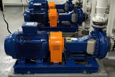
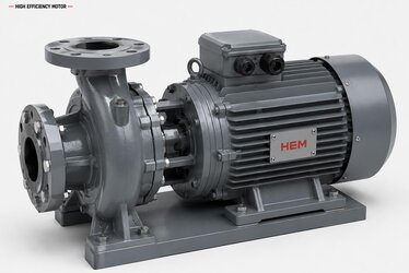
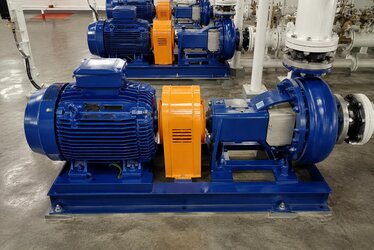
When it comes to carrying pressurized water from an apartment building's water tank up to the top floor, feeding a high-pressure washing line in an industrial plant, or raising the mains pressure in a booster (hydrophore) system, multistage vertical pumps come into play. The heart of these pumps is the electric motor that runs directly coupled to the pump shaft. In a multistage vertical pump, each stage (each impeller) increases the pressure a little further; as the stages are stacked on top of one another, the total system pressure rises. This very structure is what makes motor selection different from that of an ordinary pump: you must choose the motor not just by "how many kW" but also in the correct flange type and at the correct speed. Otherwise the motor will not seat mechanically onto the pump, the mounting will not fit, and the system cannot be assembled at all. In this article we address multistage vertical pump motor selection with its technical details, focusing on high-pressure and booster applications. As a manufacturer and seller of electric motors, we supply pump motors suited to these applications in the correct flange and speed.
Selecting a motor for a multistage vertical pump fundamentally differs from selecting a general-purpose industrial motor. In a standard foot-mounted (B3) motor the load is transmitted by a coupling or belt-and-pulley; in vertical pumps, by contrast, the motor is seated vertically on top of the pump and the shaft runs directly coupled. For this reason, the flange dimensions, shaft diameter, speed and protection class must all be perfectly compatible with one another. If even one parameter does not fit, no matter how powerful a motor you choose, the system will not work.
How Does a Multistage Vertical Pump Work?
A multistage vertical pump consists of several stacked impeller and diffuser stages. The first stage, which draws the water in, raises the pressure a little and passes it on to the next stage. Because each stage increases the pressure step by step, as the number of impellers grows, the head (Hm) the pump can reach also grows. For this reason, of two pumps delivering the same flow rate, the one with more stages can produce much higher pressure. The system logic is built on keeping the flow rate (Q) constant and managing the pressure through the number of impellers.
The motor seats vertically on top of this stacked structure and turns the pump shaft directly. The hydraulic load coming from the water side of the pump is reflected directly in the motor's rated torque. Consequently, the motor's power is calculated according to the product of the required flow rate and head, the density of the water, and the inverse of the pump efficiency. In practice, the motor power is determined by adding a safety margin on top of the shaft power that corresponds to the operating point on the curve provided by the pump manufacturer.
Hydrophore (Booster) Applications
Booster, that is, hydrophore systems, are used to raise the existing mains or tank pressure to the required level. Multistage vertical pumps are preferred for sending water to the upper floors of an apartment building, to a hotel's hot-water line, or to a point in an industrial process that requires high pressure. In these applications the pump frequently switches on and off, or it is held at constant pressure by a variable frequency drive (VFD). The motor must suit this duty regime, be resistant to frequent starts and be suitable for continuous operation. When renewing an existing hydrophore motor, our article on hydrophore motor replacement and selection from the nameplate is a useful guide for one-to-one matching from the nameplate data.
High-Pressure Water and Washing Lines
In applications such as industrial washing, reverse-osmosis feed, boiler feed water and water supply for high-rise buildings, multistage vertical pumps provide high head. In these lines it is important that the motor runs at continuous load and high efficiency, because the pumps generally turn for long hours and are responsible for a large part of the energy consumption. For the advantage that frequency-controlled operation offers in terms of energy saving, you can review our article on frequency-controlled hydrophore and booster pumps.
The Correct Flange Type: Why Will the Motor Not Seat on the Pump?
In multistage vertical pumps the motor is connected to the pump body via a flange. The most commonly used connections are B5 (FF flange) and, in vertical-shaft applications, the V1 mounting position. The flange's bolt-circle diameter, centering spigot diameter and shaft diameter must match the pump's connection interface exactly. Even if a motor is at the correct kW and the correct speed, if the flange dimension does not fit it cannot be bolted to the pump; if the shaft diameter or key dimension does not match, the coupling will not seat.
- Flange type (B5/FF): Must have the same bolt-circle and spigot diameter as the pump's connection flange.
- Mounting position (V1): Shaft pointing down, vertical mounting. It is standard in vertical-shaft pumps; the bearings and oil seal are selected to suit this position.
- Shaft diameter and key: Must be of a diameter and have a keyway that fit the pump coupling.
- Axial load: In vertical operation the axial thrust load of the water and the impellers bears on the bearings; bearing life must be assessed accordingly.
For this reason, in the selection of a vertical pump motor the flange and shaft interface is at least as decisive as the power. To choose the correct flange type, the connection dimensions in the pump model's technical documentation are taken as the basis. On the subject of flange types and dimensions, our article on flange type FF/FT and hole dimension selection provides detailed information.
Choosing the Correct Speed: 2 Poles or 4 Poles?
In multistage vertical pumps the speed directly determines the head and the flow rate. According to the pump laws, flow rate is directly proportional to speed, pressure varies with the square of speed, and power with the cube of speed. For this reason, in booster applications that require high pressure, 2-pole (approximately 2900 rpm) motors are mostly preferred; the high speed makes it possible to produce higher pressure with fewer stages.
- 2 poles (≈2900 rpm): The most common choice for high-pressure and booster applications. The high speed provides a compact pump and high head.
- 4 poles (≈1450 rpm): Preferred in applications that require lower pressure, higher flow rate and quieter operation.
Because a pump is designed for a particular head curve at a particular speed, the motor's speed must be the same as the pump's design speed. A motor at the wrong speed will either leave the pump at insufficient pressure or overload and strain the motor. If you are undecided about pole and speed selection, our article on asynchronous motor pole selection explains the basic principles.
Power Calculation: Flow Rate, Head and Efficiency
The power of a multistage vertical pump motor is calculated from the ratio of the hydraulic power to the pump efficiency. The hydraulic power is proportional to the product of the flow rate (Q), the head (Hm) and the density of the water. This hydraulic power is divided by the pump's hydraulic efficiency to arrive at the shaft power; the motor's rated power is selected by adding a safety margin on top of the shaft power. In practice:
- Flow rate (Q): The amount of water the system requires (m³/hour or l/s).
- Head (Hm): The total pressure that depends on the number of stages (mWC or bar).
- Pump efficiency: How close the operating point is to the pump's best efficiency point (BEP).
- Safety margin: So that the motor is not overwhelmed by shifts in the operating point and by transient loads.
Choosing the motor larger than necessary both raises the initial investment and lowers efficiency by running the motor at partial load. Choosing it smaller than necessary, on the other hand, overheats the motor and burns its winding prematurely. Correct power matching is the key to the system running efficiently for many years.
IP55 Protection and NPSH: Evaluate Them Together
A multistage vertical pump motor generally works in a humid, wet area exposed to the outdoors. For this reason an IP55 protection class is considered standard; IP55 indicates that the motor is protected against dust and resistant to water jets from any direction. In open-field or intensive washing environments, higher protection classes such as IP56/IP65 may also be required.
In addition, on the pump side the NPSH (Net Positive Suction Head) value must also be considered together with the motor selection. NPSH expresses the minimum suction pressure required on the pump's suction side to prevent cavitation. If the NPSH is insufficient, cavitation forms inside the pump, the impellers wear, and the motor comes under a vibrating and unstable load. This situation also fatigues the motor's bearings and shaft. On the subject of NPSH and cavitation, our article on centrifugal pump motor NPSH and cavitation offers a detailed framework.
Checklist for Correct Pump Motor Selection
- Flange type and dimension: A B5/FF flange that fits the pump's connection interface exactly.
- Mounting position: The V1 position in vertical-shaft applications.
- Speed (poles): 2 or 4 poles to match the pump's design speed.
- Power: Rated power equal to the shaft power at the operating point plus a safety margin.
- Protection class: IP55 and above according to the ambient conditions.
- Efficiency class: Low energy consumption with IE3/IE4 in continuously running pumps.
- NPSH compatibility: Planning the suction conditions so as to prevent cavitation.
Frequently Asked Questions
What is the difference between a vertical pump motor and a standard foot-mounted motor?
A standard foot-mounted (B3) motor stands on the floor and transmits its load through a coupling or belt. A vertical pump motor, on the other hand, is connected by a flange vertically on top of the pump (usually in the V1 mounting) and the shaft runs directly coupled. For this reason the vertical motor's flange dimension, shaft diameter and mounting position must be perfectly compatible with the pump; otherwise it will not seat mechanically. Furthermore, because in vertical operation the axial thrust load bears on the bearings, the bearing selection is also different.
In a multistage pump, which motor speed gives higher pressure?
According to the pump laws, pressure rises with the square of speed. For this reason, in booster applications that require high pressure, 2-pole (approximately 2900 rpm) motors are generally preferred; the high speed provides higher pressure with fewer stages. However, the motor's speed must always be the same as the pump's design speed; running the pump at a different speed degrades its performance.
How do I determine the power of the pump motor?
The motor power is found by dividing the hydraulic power, obtained from the product of the required flow rate (Q), the head (Hm) and the density of the water, by the pump efficiency, with a safety margin added on top. If you are renewing an existing pump, the nameplate values (kW, speed, flange) are the starting point; in a new system the pump manufacturer's flow-head curve is taken as the basis. If you send us your system information or the nameplate of the existing motor, we will select the motor together in the correct power, speed and flange type.
Request a Quote
Hydrophore station, high-pressure water line or booster system; for your multistage vertical pump we supply the correct pump motor in the correct flange, speed and protection class. With IP55 protection, V1 vertical mounting, the correct pole-speed and a high efficiency class, we optimize together both the pressure performance and the energy efficiency of your system. Send us your pump model and operating point; let us determine the suitable motor together. For all our electric motor solutions you can visit our homepage, and you can submit your request through our contact page.