 English
 Türkçe

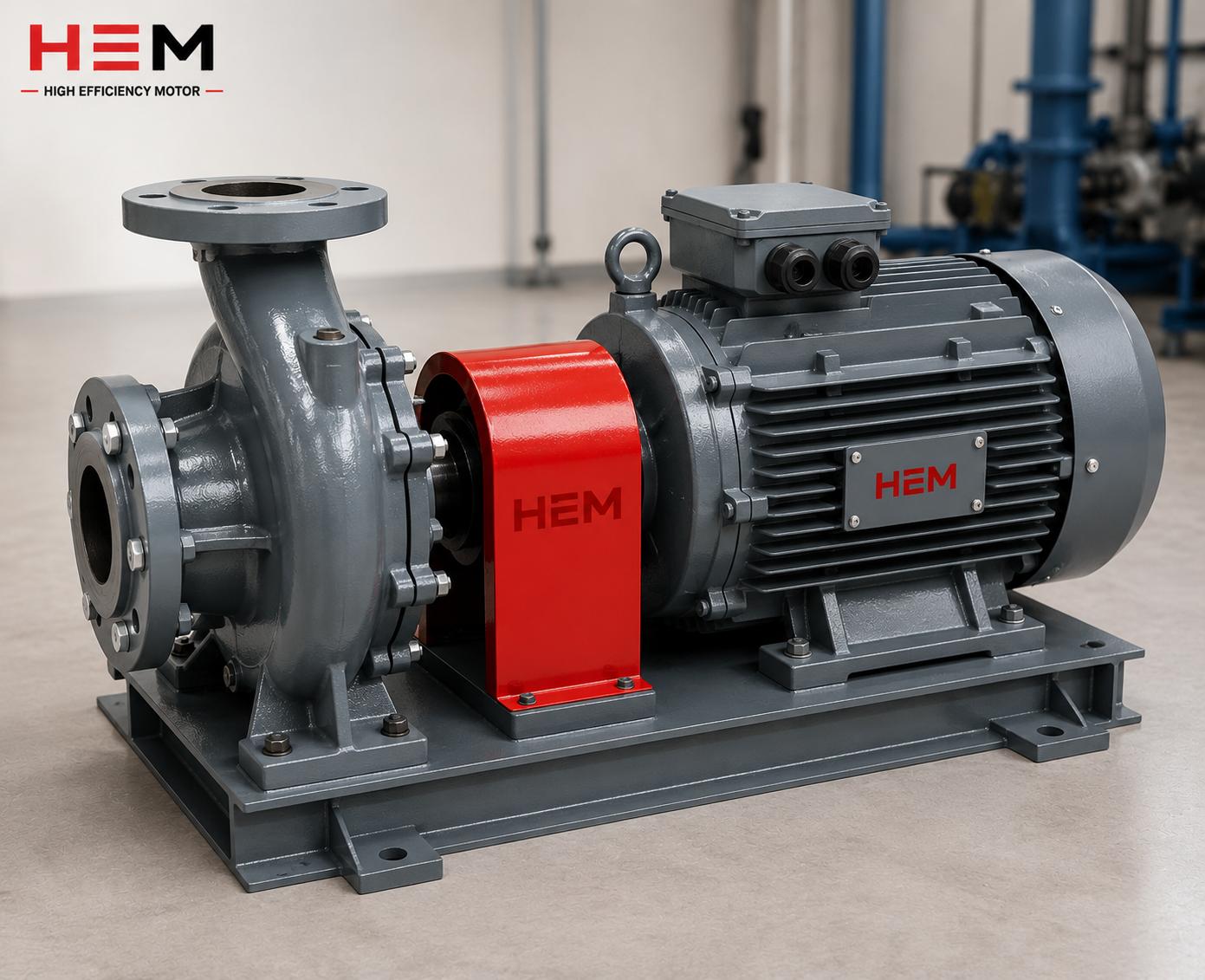
IE5 ultra premium efficiency synchronous reluctance motors (SynRM) have become an attractive option for plants that want to cut energy costs. However, the correct operation of these motors requires a procurement and installation discipline different from that of classic asynchronous motors. SynRM motors run only with a suitable frequency inverter; this makes the terminal box, cable selection and EMC earthing critical for efficiency and reliability. In this article we cover terminal box connection, drive output cable selection, EMC earthing and the correct procurement approach for IE5 synchronous reluctance motors.
Why Is Cabling More Critical on a SynRM Motor?
The rotor of a synchronous reluctance motor has no permanent magnets or windings; efficiency comes from the magnetic reluctance difference of the rotor. This structure frees the motor from magnet supply risk and provides high efficiency; we explained the basis of this in our article on the magnet-free rotor and supply advantage. However, SynRM cannot run directly from the mains; it always needs a suitable drive. We covered the reason for this in our article on why a SynRM motor does not run without a drive.
The need to run with a drive makes cabling more sensitive than on an asynchronous motor. The drive's high-frequency switching creates high dv/dt pulses and leakage currents in the motor cable. Wrong cable or incorrect earthing can lead to EMC problems, bearing currents and drive faults. For this reason the terminal and cable side of an IE5 motor is the link in the chain that carries the motor's efficiency advantage into the field.
Drive and Installation Compatibility
When migrating to an IE5 motor, the drive parameters, cable and earthing must be evaluated together. We compiled the checks that should not be skipped during commissioning in our article on the drive and installation compatibility commissioning checklist. In a correctly set-up system, a SynRM motor maintains its high efficiency even at part load.
Terminal Box Connection: Basic Rules
The terminal box is the motor's electrical "gateway" and the point where the drive output meets the motor winding. The points to watch for a correct connection are as follows:
- Phase sequence and nameplate: On SynRM motors, the direction of rotation and phase connection are handled together with the drive parameters. The connection diagram on the motor nameplate and the drive settings must be compatible.
- Earth terminal: The terminal box must have a separate, sound protective earth (PE) connection; this point must be clean, oxide-free and low-resistance.
- IP protection: The terminal box cover and gland entries must be sealed in a way that does not compromise the motor's IP protection class.
- Tightening torque: Terminal bolts must be tightened to the correct torque; a loose connection causes heating and voltage drop, while overtightening damages the terminal.
The physical connection details of the terminal box largely overlap with the principles on asynchronous cast iron motors; you can find gland selection and IP protection in our article on terminal box, IP protection and gland selection. The difference on the SynRM side is the characteristics of the drive output cable and EMC earthing.
Drive Output Cable Selection
The cable between the drive and the motor is not an ordinary supply cable. Because of the high-frequency switching, this cable must be specially selected from both a mechanical and an electromagnetic point of view:
- Shielded cable: Using symmetrical shielded motor cable at the drive output reduces emitted electromagnetic noise and leakage current problems.
- Cross-section and voltage drop: The cable cross-section must be chosen according to motor current and distance; voltage drop must be taken into account over long distances.
- Cable length: As the drive-motor distance lengthens, the dv/dt effect and capacitive leakage increase. A dv/dt or sine filter may be needed on long cables.
- Separate routing: The motor power cable must be routed separately from signal and encoder cables; it must not run in parallel in the same duct.
Cable selection is also part of managing the high-frequency leakage current produced by the drive; we covered the protection side of this topic in our article on motor protection and relay selection.
EMC Earthing: 360-Degree Termination
EMC earthing is one of the most frequently neglected yet most important details of a drive motor system. The shield of the shielded motor cable must not be connected to earth at only one point; it must be terminated 360 degrees (around the entire circumference of the cable) with an EMC gland at the entry to the terminal box. In this way the high-frequency leakage current finds a low-impedance path and does not flow through unwanted routes (bearing, frame, RCD).
- Earthing at both ends: The shield must be earthed 360 degrees at both the drive and the motor end.
- EMC gland: Instead of a standard gland, an EMC gland that earths the shield with circumferential contact must be used.
- Short earth path: Earth connections must be as short and low-impedance as possible.
Correct EMC earthing also reduces early failures caused by bearing currents. You can find the motor-side earthing application in detail in our article on motor earthing and electrical safety.
Bearing Currents and Shaft Earthing
As with all drive-operated motors, high-frequency switching can create a voltage on the shaft of SynRM motors too. This voltage can punch through the oil film in the bearing, causing small discharges and, over time, wear (fluting) on the bearing surface. Correct EMC earthing greatly reduces this risk; where necessary, additional measures such as insulated bearings or a shaft grounding brush are brought into play. These measures allow the motor to maintain its efficiency advantage for many years. We covered the general factors affecting bearing life and the selection of insulated bearings in our article on bearing type, life and insulated bearings.
The maintenance of a SynRM motor is in some respects simpler than that of an asynchronous motor, because there are no magnets or windings on the rotor; however, the drive dependency brings cable and earthing discipline to the fore. In a correctly set-up system, maintenance is largely reduced to bearing and cooling checks. You can find the maintenance and fault management of a SynRM motor in detail in our article on SynRM motor maintenance and fault management.
The Supply Difference Between SynRM and Permanent Magnet (PM) Motors
The IE5 efficiency class is reached with two main technologies: synchronous reluctance (SynRM) and permanent magnet (PM) motors. Both offer high efficiency; but there are some differences on the supply and terminal/cable side. Since PM motors have magnets on the rotor, even when the motor is stopped a turning rotor can produce voltage at the terminals; this requires extra care for maintenance safety. In SynRM motors, since there are no magnets, this risk does not exist and dependence on the magnet supply chain is eliminated. We detailed the differences between the two technologies in our article on the difference between SynRM and permanent magnet PM motors. In both technologies, the discipline of drive, shielded cable and EMC earthing applies; for this reason the terminal and cable side must be set up correctly regardless of the technology.
Correct Procurement: Buying the SynRM Motor Together with the System
As a HEM Motor manufacturer and seller, we recommend evaluating the IE5 synchronous reluctance motor not as an isolated product but as a whole together with the drive and installation. Your application's power, speed, load profile and existing drive infrastructure determine how fully you benefit from the motor's part-load efficiency advantage. We covered why SynRM is superior at part load in our article on the part-load efficiency curve.
An IE5 system set up with correct terminal connection, shielded cable and EMC earthing both carries the high efficiency into the field and runs reliably for a long life. You can consult our team for the right model for your application, drive compatibility and current electric motor prices, and plan the motor, cable and earthing solution together. The energy gain of an IE5 investment delivers its full return only in a correctly set-up system.
Terminal and Cabling Checklist
To set up an IE5 synchronous reluctance motor correctly with a drive, let us collect the points to watch on the terminal and cabling side in a short list:
- Are the connection diagram on the motor nameplate and the drive parameters compatible? Has the phase connection been made correctly?
- Is there a separate, clean and low-resistance PE earth terminal in the terminal box?
- Is symmetrical shielded motor cable used at the drive output?
- Has the cable shield been terminated 360 degrees with an EMC gland in the terminal box?
- Has the shield been earthed at both the drive and motor ends?
- Is the cable cross-section suitable for the motor current and distance? Has voltage drop been taken into account?
- If there is a long cable, is a dv/dt or sine filter needed?
- Has the power cable been routed separately from signal and encoder cables?
- Have the terminal bolts been tightened to the correct torque?
Each of these steps is important for carrying the high efficiency and reliability of the SynRM motor into the field. Unlike asynchronous motors, SynRM runs dependent on the drive, so terminal and cable discipline cannot be neglected. In a correctly set-up system, the motor maintains its high efficiency even at part load; wrong cabling or missing earthing both lowers efficiency and leads to EMC problems and early failures. For this reason, when evaluating an IE5 investment, you need to plan the cable, drive and earthing solution as much as the motor itself.
Frequently Asked Questions
Can I run an IE5 synchronous reluctance motor directly from the mains?
No. SynRM motors cannot start on their own and need a suitable frequency inverter for synchronous operation. They cannot be connected directly to the mains (DOL). For this reason the motor and drive must be handled as a package, and the terminal, cable and earthing must be planned together with that package.
Why should I use shielded cable on the drive output?
The drive's high-frequency switching creates electromagnetic noise and leakage current in the motor cable. Shielded cable brings this noise under control and provides EMC compatibility. Earthing the shield 360 degrees with an EMC gland in the terminal box gives the high-frequency current a low-impedance return path, reducing bearing currents and equipment problems.
Wouldn't single-point EMC earthing be enough?
In drive systems, single-point earthing does not provide a sufficiently low-impedance path for high-frequency leakage current. The recommendation is to earth the shield 360 degrees (circumferentially) at both the drive and motor ends. This approach prevents leakage current from flowing through unwanted routes and keeps the system stable from an EMC point of view.


