English
 Türkçe
The most common cause of an IE3 motor burning out is overheating; when overload, single phasing, frequent start-stop or inadequate cooling pushes the winding temperature above the insulation class, the winding is damaged quickly. An externally wired thermal relay monitors current but cannot see the real temperature of the winding. That is why temperature protection elements embedded in the winding are used on critical motors: the PTC thermistor and the PT100 (RTD). In this article we examine, from a correct-installation perspective, the difference between an embedded PTC thermistor (DIN 44082) and a PT100 in an IE3 motor, the wiring of the thermistor relay and the PT100 transmitter, the extra terminals in the terminal box, the protection class, when to choose PTC and when PT100, and the importance of thermal protection in a VFD system.
Why Is Winding-Embedded Temperature Protection Needed?
A thermal relay and motor protection circuit breaker (MPCB) that monitor the current through the motor terminals provide indirect protection: if the current is high, they assume the winding is heating up. But in some cases the winding overheats while the current looks normal; for example if the cooling fan is blocked, the ambient temperature is very high, or the motor cannot cool sufficiently with its own fan at low speed. In these cases external current protection falls short. An embedded sensor measures temperature directly, at its source, and provides the most reliable protection. We covered current-based protection in our thermal relay and fuse selection article and our motor protection circuit breaker (MPCB) article; embedded temperature protection complements, not replaces, these.
What Is a PTC Thermistor (DIN 44082)?
A PTC thermistor is a positive temperature coefficient semiconductor sensor. Up to a certain threshold temperature (nominal anneal temperature, NAT) its resistance stays low and almost constant; once this threshold is exceeded its resistance rises very rapidly and steeply. PTC thermistors are made to the DIN 44081/44082 standard. One is usually embedded in each of the motor's three phase windings and they are connected in series, so overheating in any phase is detected. A PTC is not a measurement sensor but a threshold (switch) element: it does not give the temperature as a number, only the information "is the threshold exceeded or not".
How is a PTC connected? (Thermistor relay)
PTC thermistors cannot cut the contactor directly; a thermistor protection relay sits in between. The relay continuously monitors the resistance of the PTC chain. When the resistance exceeds the threshold and rises steeply, the relay changes its output contact and stops the motor by cutting the contactor coil. The connection is set up with this logic: the PTC terminals in the motor's terminal box (usually marked) are connected to the input terminals of the thermistor relay; the relay's output contact is added in series to the contactor's control circuit. The relay also faults if the PTC chain is short-circuited or open, which increases sensor safety.
What Is a PT100 (RTD)?
The PT100 is a platinum resistance temperature sensor (RTD). It shows exactly 100 ohms at 0 degrees and its resistance increases along a predictable, near-linear curve as temperature rises. Its fundamental difference from the PTC is this: the PT100 gives a continuous and numerical temperature measurement. So you can read the instantaneous temperature of the winding in degrees. This provides continuous monitoring, recording (trend) and early warning beyond threshold protection. PT100 sensors are also embedded in the winding or placed near the bearing to measure bearing temperature. We covered the whole of winding and bearing temperature monitoring in our motor winding temperature monitoring article.
How is a PT100 connected? (Transmitter / reader)
Because the PT100's resistance corresponds to a temperature, a reading device is needed: a PT100 transmitter, a temperature indicator or a PLC RTD input module. The connection is usually made with 3 wires (4 wires in some precise applications) so that cable resistance does not distort the measurement. The PT100 terminals in the terminal box are connected to the transmitter/reader; the transmitter converts the temperature into a signal (for example 4-20 mA) and sends it to the PLC or panel. The winding temperature is thus continuously monitored; at the set alarm and trip thresholds the system warns or stops the motor.
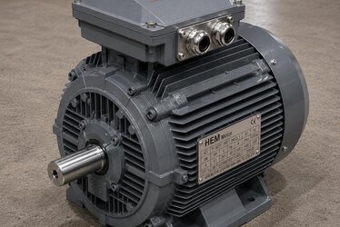
Extra Terminals in the Terminal Box and Correct Installation
On an IE3 motor with temperature protection elements, the terminal box has separate, marked signal terminals alongside the main power terminals (U-V-W). For correct installation of these terminals:
- Separate cabling: PTC/PT100 signal cables should be routed separately from power cables; especially in a VFD system the signal cable should be shielded.
- Correct terminal matching: The terminals of the three-phase PTC chain and the 3-wire PT100 connection should be wired according to the markings on the motor nameplate/terminal diagram.
- Sealing and IP protection: The terminal box cover and glands for the extra terminals should be closed without breaking the IP protection.
We covered the terminal box's own sealing and cable entry in our terminal box and cable connection article. You can find the star/delta bridging on the main power side in our IE3 winding connection article.
When PTC, When PT100?
Both are valuable but answer different needs:
- Choose a PTC thermistor: If the goal is a simple, reliable and inexpensive over-temperature cut-off. If stopping the motor when the threshold is exceeded is enough, PTC + thermistor relay is a common and economical solution on standard pump/fan/conveyor motors.
- Choose a PT100: If you want to continuously monitor, record, trend and get early warning of the winding temperature. On critical process motors, high-power motors and continuously running drives whose downtime is expensive, PT100 + transmitter is the more correct choice.
On many critical motors the two methods are used together: PT100 for continuous monitoring, PTC for definite tripping. To understand how hard each motor is being worked you need to know the duty type; we covered this in our duty type (S1-S6) article and the temperature rise class in our temperature rise class article. You can find the relationship of the insulation class (F/H) with temperature in our winding and insulation class article.
Protection Logic: Alarm Threshold and Trip Threshold
A correct temperature protection installation is most valuable when set up with two-stage logic rather than a single cut-off point. In a continuously measuring system such as the PT100, two thresholds are defined:
- Alarm threshold (early warning): When the winding temperature rises above normal but is not yet dangerous, a warning is given to the operator. This allows a chance to intervene before stopping the motor: it buys time to reduce the load, check the cooling or investigate the cause.
- Trip threshold (definite protection): When the temperature approaches the safe limit of the insulation class, the motor is automatically stopped, protecting the winding from permanent damage.
This two-stage approach both preserves production continuity and keeps the motor safe. In simple systems using only a PTC there is a single stage (trip); if early warning is wanted, either a PTC set with two different threshold temperatures or continuous monitoring with a PT100 is needed. To set the thresholds correctly, it is essential to know the motor's insulation class (F or H) and the corresponding safe temperature limit; the temperatures permitted by F-class and H-class insulation differ, and the thresholds should be set accordingly.
The Difference Between Winding Protection and Bearing Temperature Monitoring
When temperature protection is mentioned, only the winding often comes to mind; but on high-power and critical motors the bearing temperature is also monitored with a separate PT100. While winding temperature shows electrical overload, bearing temperature gives early warning of a mechanical problem: inadequate lubrication, bearing wear or misalignment heats the bearing. So placing sensors in both the winding and the bearings on critical motors enables two different fault types to be caught early. Monitoring bearing temperature is a cornerstone of predictive maintenance, especially on continuously running drives whose downtime is expensive.
Why Is Thermal Protection More Critical in a VFD System?
Thermal protection is even more important on an IE3 motor running with a variable frequency drive (VFD), because:
- Cooling decreases at low speed: Because the motor's own fan is on the shaft, when speed drops the fan slows and cooling weakens. In low-speed running requiring constant torque, the winding can overheat. An external forced cooling fan may be needed here; we covered the topic in our external forced cooling fan article.
- Harmonic-induced extra heating: The harmonics the VFD produces create extra loss and heating in the motor. We examined this extra heating in our VFD harmonic heating and bearing current article.
- Current monitoring can be misleading: At variable speed, setting current-based protection becomes harder; the embedded sensor is the most reliable reference.
So in VFD systems, connecting the winding PTC/PT100 signal directly to the drive or PLC is strong protection. We covered grounding and shielded cable on a VFD motor in our grounding and EMC article. You can find the effect of frequent start-stop (jogging) on heating in our jogging and inching article.
Frequently Asked Questions
What is the fundamental difference between a PTC thermistor and a PT100?
A PTC thermistor is a threshold (switch) element: when a certain temperature is exceeded its resistance rises steeply and the thermistor relay stops the motor; it does not give the temperature as a number. A PT100 is a platinum resistance sensor and gives a continuous, numerical temperature measurement; with a transmitter/reader you can monitor, record and get early warning of the winding temperature in degrees. PTC is for simple, economical tripping; PT100 is for continuous monitoring.
Can I connect the PTC thermistor directly to the contactor?
No. A PTC is not a switch that cuts the contactor coil directly; a thermistor protection relay is needed in between. The PTC terminals in the motor's terminal box are connected to the thermistor relay input, and the relay's output contact is connected in series with the contactor's control circuit. The relay also faults when there is an open circuit or short in the PTC chain, increasing protection safety.
Why is thermal protection more critical on a VFD-driven motor?
With a VFD, at low speed the motor's own fan slows and cooling decreases; in addition harmonics create extra heating. Setting current-based protection at variable speed is also harder. So a PTC/PT100 embedded in the winding is the most reliable protection because it measures temperature at its source, and its signal should be connected directly to the drive or PLC. An external forced cooling fan should be added if needed.
Get a Quote for Your IE3 Motor and Temperature Protection
We are by your side to choose the right temperature protection (PTC or PT100) for your IE3 motor and install it correctly in the terminal box. Share your application's power, speed, duty type and VFD situation; we will recommend a suitable IE3 motor together with a winding sensor option. Reach us now on +90 (532) 345 49 86 or via our contact page. Explore our IE3 motor range on our IE3 electric motor page, and all products on our homepage and our IE3 blog category.
Purchasing and Installation Checklist
- Is a PTC (DIN 44082) or PT100 sensor requested in the motor winding and written into the order?
- Has a thermistor protection relay for the PTC, or a transmitter/reader for the PT100, been procured?
- Are the extra signal terminals in the terminal box marked and cabled separately?
- Is the signal cable shielded in a VFD system?
- Is the PT100 connected with 3 wires (4 wires if required)?
- Has the need for an external forced fan for low-speed cooling been assessed?
- Are the alarm and trip thresholds set according to the insulation class (F/H)?