English
 Türkçe
Selecting an IE3 electric motor at the correct power is only half the job for a sound installation. The other half is sizing the panel, the busbar system and the supply cable correctly according to the rated current that motor draws. A cable of insufficient cross-section leads to voltage drop, heating and, over time, a fire risk; an incorrectly set thermal protection either stops the motor needlessly or fails to protect it in a real overload. IE3 efficient motors, thanks to their high efficiency, run with lower losses at the same power; nevertheless, correct panel and cable selection still depends on the rated current and application conditions. In this guide we address the selection of panel, busbar and cable cross-section according to an IE3 motor's rated current, under the headings of voltage drop, thermal setting and error-free supply.
Rated Current: The Starting Point of All Selections
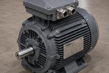
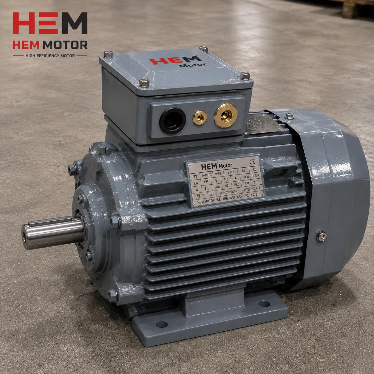
The rated current on the motor nameplate (usually given for 400 V) is the current that motor draws from the grid at full load. The entire selection of panel, busbar and cable starts from this value. Rated current depends on the motor's power, voltage, power factor (cosφ) and efficiency. Because IE3 motors are highly efficient, they run with lower losses at the same mechanical power, but the current value must still be verified from the nameplate; calculating by assumption leads to incorrect cross-section selection.
Therefore the first step is always to read the motor nameplate correctly. To interpret the power, voltage, current, cosφ and efficiency values on the nameplate correctly, our article on reading the IE3 motor nameplate: kW, speed, cosφ and efficiency is a fundamental guide.
Do Not Forget the Starting Current Effect
The motor's rated current is at full load; but at the moment of start-up this current rises to several times that value. While the cable and busbar are sized for the continuous current, protection devices and breakers must be selected to tolerate the starting current as well. Otherwise the protection trips at every start. For this reason the starting method (direct, star-delta, soft starter) also affects cable and panel selection.
Cable Cross-Section Selection: Current Carrying and Voltage Drop
In cable cross-section selection, two independent criteria must be satisfied together. The first is that the cable can carry the motor's rated current without heating (current carrying capacity). The second is that the voltage drop along the length of the cable stays within an acceptable limit.
Current Carrying Capacity
The current a cable can carry depends on its cross-section, the installation method (tray, conduit, overhead), the ambient temperature and the number of cables laid together. A cable of the same cross-section carries less current in a hot, crowded tray. Therefore cable selection is done not only with the question "how many amps" but also "under what conditions". An insufficient cross-section heats the cable, ages the insulation and eventually leads to failure.
Voltage Drop
Because of the cable's resistance, the voltage reaching the motor is somewhat lower than the voltage at the panel output. This difference increases with cable length and current. If the voltage reaching the motor is low, the motor is forced to run at low voltage; this causes the torque to drop, the current to rise and heating to occur. Especially in long-distance supplies, the cable cross-section is increased not only for current carrying but also to keep the voltage drop within the limit. You can find the effects of motor voltage tolerance and grid fluctuation in detail in our article on voltage tolerance and grid fluctuation in IE3 three-phase motors.
Thermal Protection Setting: Protecting the Motor Correctly
The motor protection relay or thermal breaker protects the motor against overload current. The setting value of this device is made according to the motor's rated current. Too low a setting stops the motor needlessly in normal operation; too high a setting fails to protect the motor in a real overload and allows the winding to burn. The correct setting is determined according to the motor's nameplate current and service factor.
The Relationship with the Service Factor
The service factor shows how much the motor can be briefly loaded above its rated power. This factor is also taken into account when setting the thermal protection; a motor with a high service factor tolerates momentary load peaks better. We address the role of the service factor in selection and protection in our content on service factor (SF) and overload capacity in IE3 motors.
Panel and Busbar System: Sizing in a Collective Installation
In a motor control centre (MCC) feeding more than one motor, the main busbar system is sized to carry the total current of all the motors. The busbar cross-section is determined by the current it carries and its short-circuit withstand. Heating inside the panel directly affects busbar and cable selection; in a crowded panel with poor ventilation, the same cross-section carries less current.
Terminal and Connection Quality
Even a well-selected cable turns into a hot spot if it meets a loose or unsuitable connection in the motor terminal box. The terminal connection must be made with the correct tightening torque, suitable lugs and glands must be selected, and IP protection must be maintained at the connection point too. We explain making the motor terminal box and cable connection correctly in our article on motor terminal box and cable connection: IP protection and the right gland selection.
The Effect of the Starting Method on Panel Design
In direct-on-line starting the starting current is high and protection devices are selected accordingly. When star-delta or a soft starter is used, the starting current is reduced, which changes the selection of devices on the supply side. We compare the choice of starting method in our article on starting AC asynchronous motors: star-delta or soft starter.
Power Factor (cosφ) and Reactive Power
Part of the current the motor draws produces mechanical work, while another part is the reactive power spent to establish the magnetic field. The power factor (cosφ) shows the relationship between these two components. A low power factor means that a higher current is drawn from the grid for the same mechanical power, which creates an unnecessary load on the cable and busbar. IE3 motors generally run with a higher power factor thanks to a well-designed winding and magnetic circuit, but cosφ can drop especially at low load.
If there are several motors in the facility and the overall power factor is low, the reactive power is corrected with a compensation panel. This both reduces the current drawn from the grid and prevents unnecessary loading of cables and busbars. When sizing the panel and cable, reading the motor's actual power factor from the nameplate and calculating the total load accordingly prevents over-sizing or under-sizing errors.
Harmonics and the Frequency Drive Effect
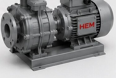
If the motor runs with a frequency drive, harmonic currents arise on the supply side. These harmonics can cause additional heating in cables and busbars; therefore the supply installation of drive-fed motors is sized to also account for the harmonic effect. In addition, the neutral conductor and earthing design must be done more carefully in systems with harmonics. In drive systems, the cable cross-section must be evaluated not only by the current at the fundamental frequency but together with the harmonic content.
Earthing and Safety
An inseparable part of panel and cable selection in a motor installation is also the earthing and protective conductor. The motor body is earthed with a protective conductor of suitable cross-section so that it does not remain live in the event of a fault. The cross-section of the protective conductor is chosen in proportion to the cross-section of the phase conductor. Good earthing is essential for both personal safety and the correct operation of overcurrent protection devices.
In motors working in dusty and humid field conditions, protecting the connection points in the terminal box and the earthing terminals against corrosion is important. A loose or oxidized earthing connection both creates a safety risk and leads to failure over time. Therefore, when selecting the panel and cable, connection quality and earthing integrity must be addressed as part of the design.
Error-Free Supply: Pre-Order Check
Even if the panel and cable selection is done correctly, if the wrong motor is supplied the whole design is wasted. Therefore the following information must be clear before ordering:
- Power and speed: kW and RPM; pole count.
- Rated current and voltage: nameplate current for 400 V, 690 V connection if required.
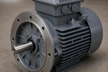
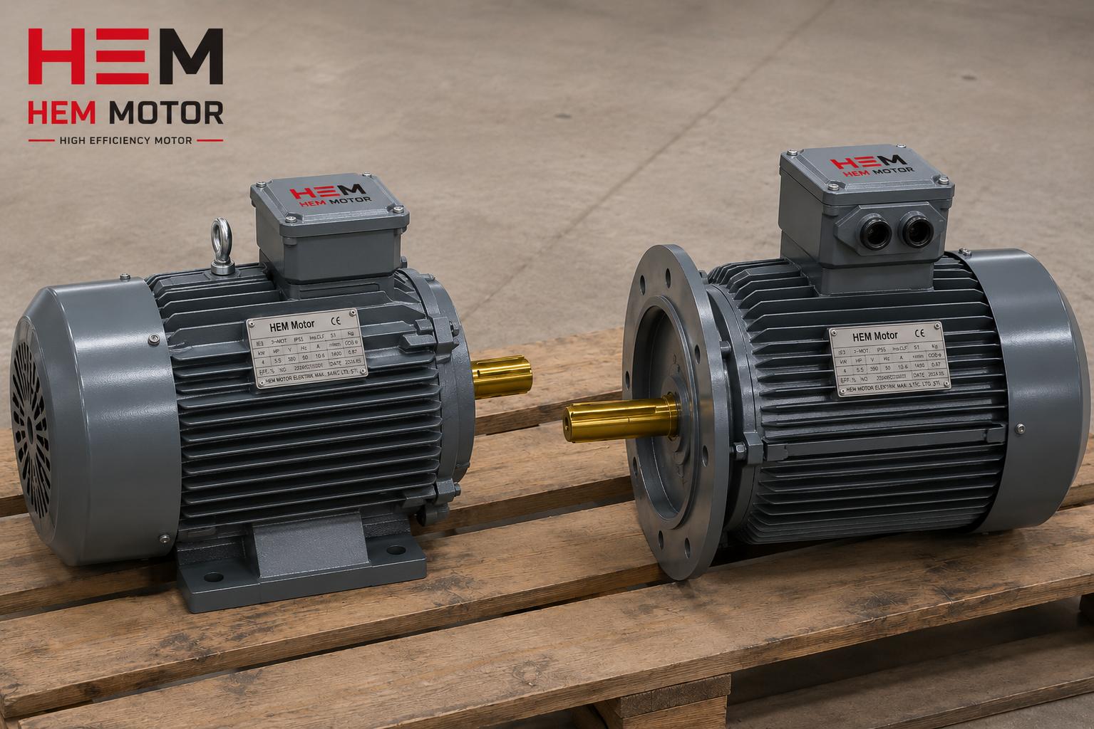
- Efficiency class: IE3 or IE4; regulatory compliance.
- Mounting type: B3 foot-mounted, B5 or B35 flange-mounted; shaft diameter and frame size.
- Protection class and insulation: IP55 standard, IP65 if required; F-class insulation.
With this information, both the motor and the supply installation are compatible with each other. In IE3 and IE4 efficiency class, over a wide power range from 0.55 kW to 355 kW, with a cast iron body and 100% copper winding, you can supply motors quickly; for a motor suited to your application and current electric motor prices, you can contact our product team.
Frequently Asked Questions
Should I select the cable cross-section by current or by length?
By both. First the cable must have a cross-section that can carry the motor's rated current without heating; this is evaluated together with the installation method, ambient temperature and the number of cables laid together. Then the voltage drop along the cable length is checked; over long distances the cross-section is chosen larger than the current carrying requirement to keep voltage drop within the limit. Whichever criterion demands the larger cross-section is the determining one.
According to which current should I set the thermal protection?
The setting is made according to the rated current on the motor nameplate, with the service factor taken into account. Too low a setting stops the motor needlessly in normal operation; too high a setting leaves it unprotected in a real overload. The correct setting is determined so that it does not stop the motor at normal load peaks but disconnects it in time during a real overload.
Since an IE3 motor draws lower current, can I use a thinner cable?
Because IE3 motors are highly efficient, they run with lower losses at the same mechanical power, but cable selection must always be made according to the actual rated current on the nameplate and the installation conditions. Saying "efficient motor, a thin cable is enough" by assumption is incorrect; the correct approach is to read the nameplate current and apply the current carrying and voltage drop criteria together.