English
 Türkçe
When you decide to run an IE3 electric motor on a variable frequency drive (VFD), the electrical environment the motor faces becomes completely different from that of a motor connected directly to the mains. A mains-fed motor sees a smooth, clean sine-wave voltage; a drive-fed motor, on the other hand, encounters sharp, steep-edged voltage pulses produced by IGBT semiconductors switching thousands of times per second. This is exactly where the concepts of inverter-duty winding and du/dt endurance move to the center of motor selection and correct procurement. A poorly chosen winding structure can lead to winding breakdown and unexpected stoppages within months in a drive application.
As an electric motor manufacturer and supplier, our goal is to ensure that motors intended for drive operation are supplied with the correct winding insulation, the correct phase-to-phase separation structure and, where necessary, insulated bearings. In this guide, we examine in detail how the drive's voltage pulse (du/dt) and the overvoltage caused by cable reflection stress the motor, what an inverter-duty winding means, why phase-to-phase insulation is critical, and what should be written into the specification at the purchasing stage. The aim is for you to ask the right questions when requesting a quotation and to procure a long-lasting, reliable motor for drive operation correctly the first time.
What Is a VFD Voltage Pulse (du/dt) and Cable Reflection?
A frequency drive delivers the constant DC bus voltage to the motor as rapidly switched pulses. The rise time of these pulses is very short; that is, the voltage jumps from zero to its peak value in a very short interval. This rapid rate of change is called du/dt and is expressed in volts per microsecond. The steeper the du/dt, the higher the voltage imposed on the first turns of the motor winding.
There is also the cable side. The cable between the drive and the motor behaves like a transmission line for high-frequency pulses. When the pulse reaches the motor, part of it is reflected back due to the motor's high impedance and overlaps with the incoming pulse, raising the peak voltage. In long cables, this reflection becomes so pronounced that the peak voltage seen at the motor terminals can reach nearly twice the DC bus voltage. This phenomenon is called cable reflection and is the main cause of premature fatigue of the phase-to-phase insulation.
- Short rise time (du/dt): Causes the voltage to distribute unevenly among the first turns of the winding; the greatest stress is at the winding entry.
- Cable reflection: Long motor cables can raise the peak voltage at the terminals to nearly twice the DC bus value.
- Switching frequency: A high switching frequency means more pulses per unit time and therefore more fatigue on the insulation.
- Phase-to-phase voltage: When the pulses of two different phases coincide, the phase-to-phase insulation sees the highest voltage stress.
Our article on VFD with asynchronous motor selection, in which we discuss the basic logic of a drive system and when a drive is needed, is a good starting point for understanding the foundation of this subject.
Inverter-Duty Winding: The Difference from a Standard Winding
A standard asynchronous motor winding is designed for a clean sine-wave voltage and has a limited insulation margin against the steep pulses produced by a drive. An inverter-duty (drive-compatible) winding, however, is reinforced precisely for this pulsed environment. Although the difference is not visible to the eye, it shows itself in every layer of the insulation structure.
Points Reinforced in an Inverter-Duty Winding
- Reinforced wire enamel insulation: The insulation of the winding wire itself is chosen to be more resistant to high du/dt pulses and partial discharge.
- Improved phase-to-phase separators: Thicker, more durable insulation paper/film is placed between the adjacent turns of different phases.
- Better varnish impregnation: The winding is filled more completely with vacuum impregnation, reducing air voids; air voids are where partial discharge begins.
- High insulation class: F or H class insulation provides both thermal and electrical margin.
Our content on winding and insulation class F/H on IE3 motors, in which we examine the effect of insulation class on motor life and endurance in detail, makes it easier to make the right insulation decision. In a drive application, insulation class matters not only for temperature but also for electrical pulse endurance.
Why Is Phase-to-Phase Insulation Critical?
The pulses coming from the drive are not always distributed equally among the windings of the three phases. When the pulses of two phases coincide at the moment of switching, a very high instantaneous voltage occurs between the adjacent turns of those two phases. For this reason, the most common failure in drive-fed motors is a phase-to-phase short circuit. The quality and correct placement of the phase-to-phase separators directly determine the motor's life under drive operation.
The fatigue of phase-to-phase insulation is not sudden; it begins with partial discharges, gradually erodes the insulation and finally leads to breakdown. Therefore, requesting an inverter-duty winding from the outset for a motor that will run on a drive is far more economical than later incurring rewinding cost and downtime loss. Correctly making the grounding and EMC connection in drive systems is also a critical factor that extends insulation life; our article on motor grounding and EMC connection in a VFD system guides you in this respect.
Bearing Currents and the Need for Insulated Bearings
In a drive-fed motor, not only the winding but also the bearings are at risk. Fast switching creates a common-mode voltage on the shaft. When this voltage exceeds a certain threshold, it punctures the bearing oil film and causes small electrical discharges (EDM — spark erosion). Over time, these discharges create groove-like marks (fluting) and metal loss on the bearing races; the result is noise, vibration and premature bearing failure.
- Insulated bearing (usually at the non-drive NDE end): Protects the bearing by preventing the current from closing through the body.
- Shaft grounding brush: Safely conducts the voltage on the shaft to ground.
- Shielded motor cable and correct grounding: Provides a controlled return path for the common-mode current.
Our content on VFD and harmonic-induced heating and bearing currents on asynchronous motors, in which we discuss the symptoms, risks and protection methods of bearing currents in detail, clarifies which measure is needed in high-power and long-cable applications.
Cable Length, du/dt Filter and Sine Filter
The cable length between the drive and the motor directly determines the severity of the voltage pulse. The longer the cable, the higher the peak voltage caused by reflection. While an inverter-duty winding is sufficient in most cases for short cables, in long-cable applications a filter may need to be added at the drive output to protect the motor.
- du/dt filter (output reactor): Reduces the stress on the first turns of the winding by slowing the rise rate of the voltage; a common solution for medium-length cables.
- Sine filter: Makes the drive output almost a clean sine wave; used in very long cables and applications requiring sensitive insulation.
- Correct cable selection: A shielded, symmetrical motor cable improves both insulation and EMC performance.
Even if a filter is used, selecting the motor with a drive-compatible winding in the first place is the most robust solution. A filter is an additional protection layer; on its own it cannot fully protect a standard winding against steep pulses.
Cooling at Low Speed: Constant-Torque Applications
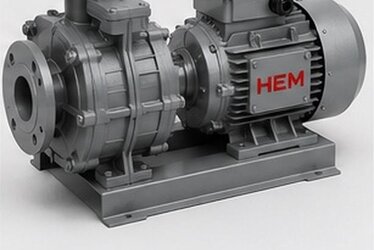
When the motor is run at low speed by the drive, the motor's own shaft-mounted fan also slows down and cooling weakens. In applications requiring constant torque (i.e. constant current and constant heat) at low speed, such as conveyors, extruders or mixers, the motor may not cool sufficiently while turning slowly. In this case, an external forced-cooling fan is needed; this fan runs at a constant speed independent of the motor's speed and guarantees cooling.
Our article on external forced-cooling fan at low speed and VFD, in which we discuss in which application forced cooling is essential and the correct sizing, helps you make the right motor selection in constant-torque applications. Insufficient cooling is a silent threat that reduces both efficiency and insulation life in a drive-fed motor.
Switching Frequency and Its Relation to Partial Discharge
The switching frequency of the drive is a parameter that directly affects the fatigue rate on the motor's insulation. A high switching frequency sends far more voltage pulses to the motor per unit time. Each pulse applies a small stress to the first turns of the winding and to the phase-to-phase insulation. Although a single pulse seems harmless, the long-term repetition of thousands of pulses per second accumulates fatigue in the insulation and sets the stage for partial discharge to begin.
Partial discharge consists of small electrical sparks that occur in the microscopic air voids within the insulation. These discharges are invisible but gradually erode and corrode the insulation material chemically over time. While this process accelerates in a standard winding, in an inverter-duty winding the air voids are minimized through vacuum varnish impregnation, so partial discharge begins much later. This is exactly where the true value of a drive-compatible winding becomes apparent: it provides many times longer life than a standard winding in the same electrical environment.
- High switching frequency: Provides quieter operation but increases fatigue on the insulation; the balance must be set correctly on the drive side.
- Air voids: Are where partial discharge begins; a well-impregnated winding minimizes this risk.
- Continuous pulse repetition: Insulation fatigue is cumulative; choosing a strong winding from the start reduces total cost of ownership.
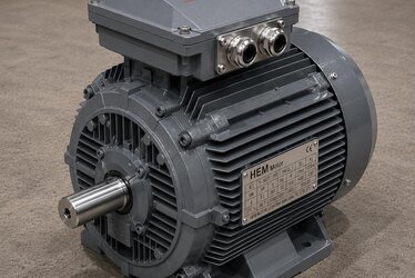
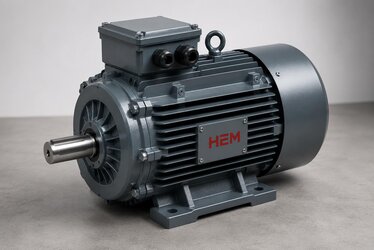
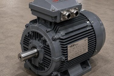
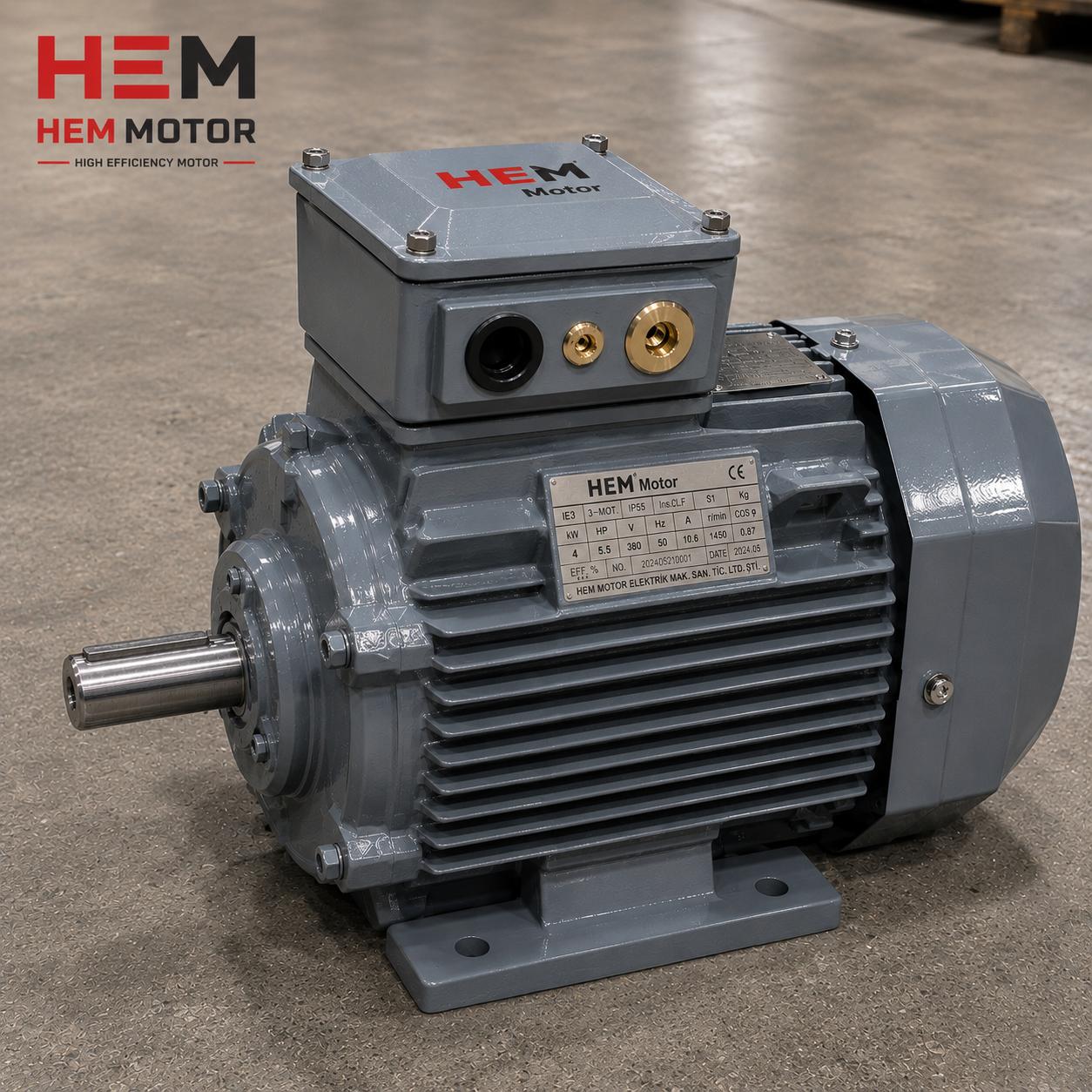
IE3 cast iron motors offer a solid foundation for drive-fed heavy-duty applications with both their mechanical strength and good cooling characteristics. In a drive system, the motor's body material is as much a part of long life as the winding structure.
Purchasing and Procurement: What Should Be Written in the Specification?
When ordering an IE3 motor that will run on a drive, clearly stating a few critical items in the specification prevents the wrong motor from arriving and avoids later rewinding cost. A standard motor nameplate may not state "VFD compatible"; therefore the requirement must be written clearly.
- Winding structure: "inverter-duty / VFD-compatible reinforced winding" should be explicitly requested.
- Insulation class: at least F, preferably H class insulation should be specified.
- Cable length and drive type: should be conveyed to the supplier to assess the need for a filter.
- Need for insulated bearing/shaft grounding: should be requested in large-frame and long-cable applications.
- If the motor will run at constant torque at low speed, an external forced-cooling fan should be requested.
- Frame, shaft diameter and mounting type: the nameplate values of the existing motor should be given for equivalent replacement.
A clear request including these items ensures a motor fully compatible with your project is supplied quickly. When you contact us for current electric motor prices, stock status and drive-compatible winding options, we match the IE3 cast iron motor suitable for your application with the correct specification. A procurement process that starts correctly means a motor that runs trouble-free for years in your drive system.
Common Mistakes in Drive-Fed IE3 Motors
- Connecting a standard-winding motor to a drive with a long cable: Cable reflection quickly fatigues the phase-to-phase insulation.
- Skipping the filter: Without a du/dt or sine filter in a very long-cable application, the motor is at risk.
- Ignoring bearing currents: If there is no insulated bearing/shaft grounding on a large frame, the bearing fails early.
- Forgetting cooling at low speed: Without a forced fan in a constant-torque application, the motor overheats.
- Not writing it in the specification: If the "VFD-compatible" request is not stated explicitly, a standard motor arrives.
Frequently Asked Questions
Does a standard IE3 motor run on a frequency drive?
In short-cable and low-switching-frequency applications, a standard F-class IE3 motor can run on a drive in a limited way. However, if a long cable, high switching frequency or continuous constant torque is involved, du/dt pulses and cable reflection fatigue the phase-to-phase insulation early. For a reliable and long-lasting solution, requesting an inverter-duty (VFD-compatible) winding is the right approach.
Why does cable length affect motor insulation?
The cable between the drive and the motor behaves like a transmission line for high-frequency pulses. When the pulse reaches the motor, part of it is reflected back and overlaps with the incoming pulse, raising the peak voltage at the terminals. The longer the cable, the higher this peak voltage, which can reach nearly twice the DC bus voltage. Using a du/dt or sine filter on long cables protects the motor.
Is an insulated bearing always needed on a drive-fed motor?
No, it is not needed on every motor. It is usually not required in small-frame and short-cable applications. However, in large-frame motors and long-cable systems, the common-mode voltage on the shaft can cause spark erosion (EDM) in the bearings. In this case, an insulated bearing at the non-drive end or a shaft grounding brush significantly extends bearing life. If you share the frame size and cable length during procurement, we can offer the right recommendation.