English
 Türkçe
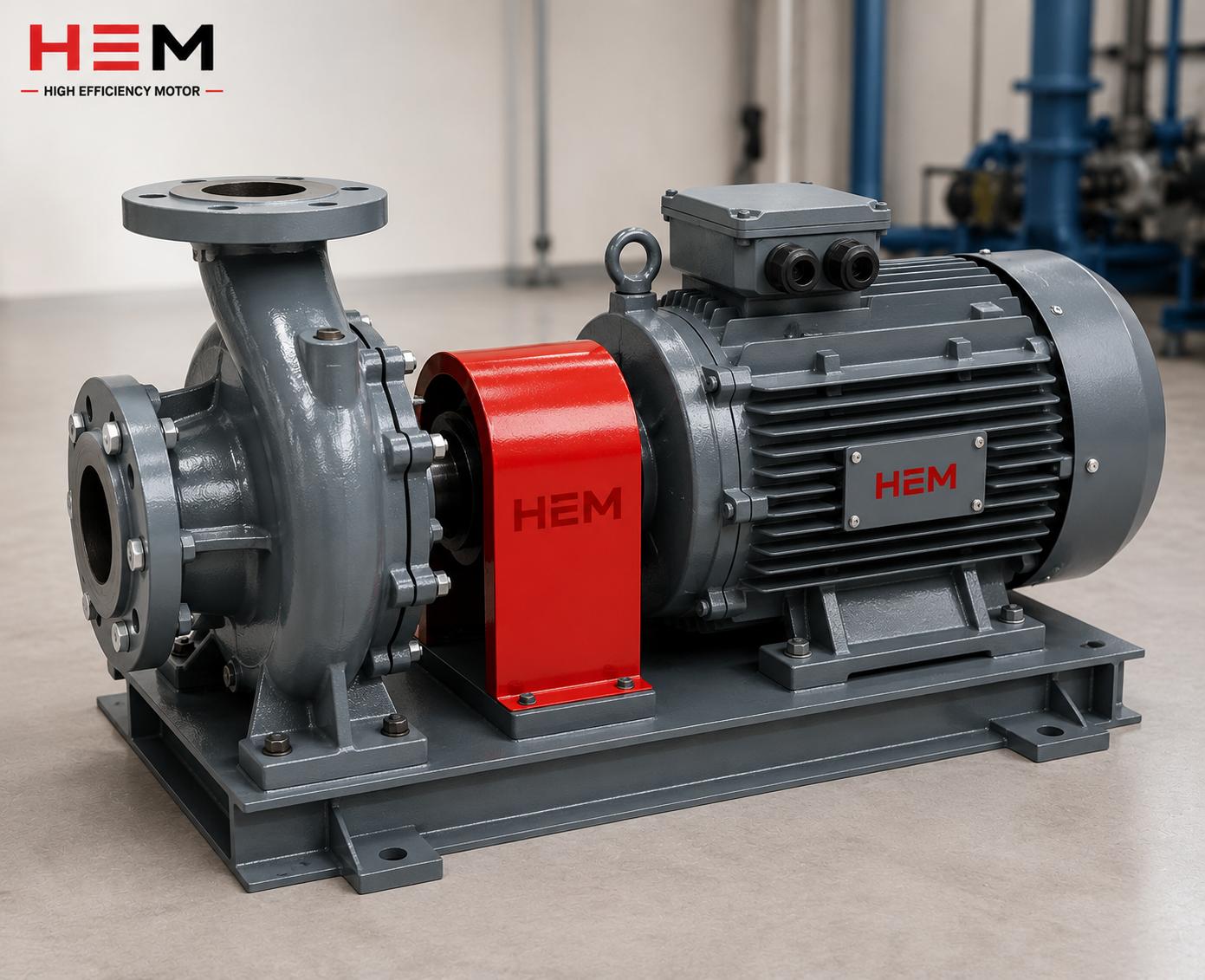
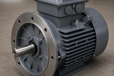
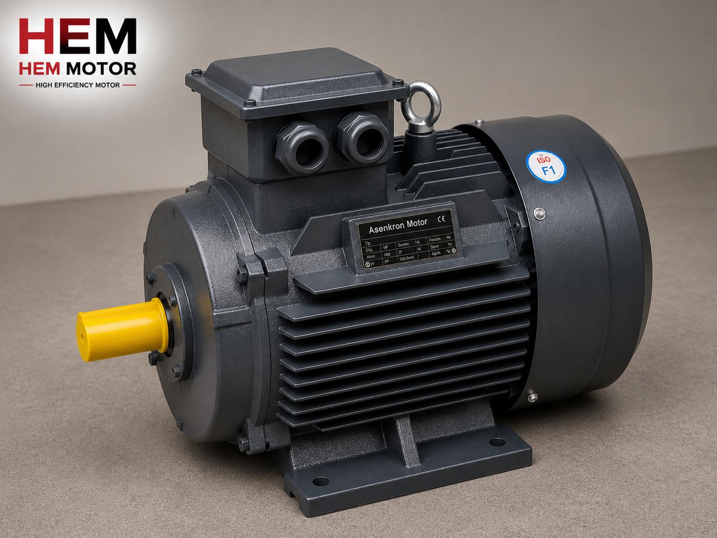
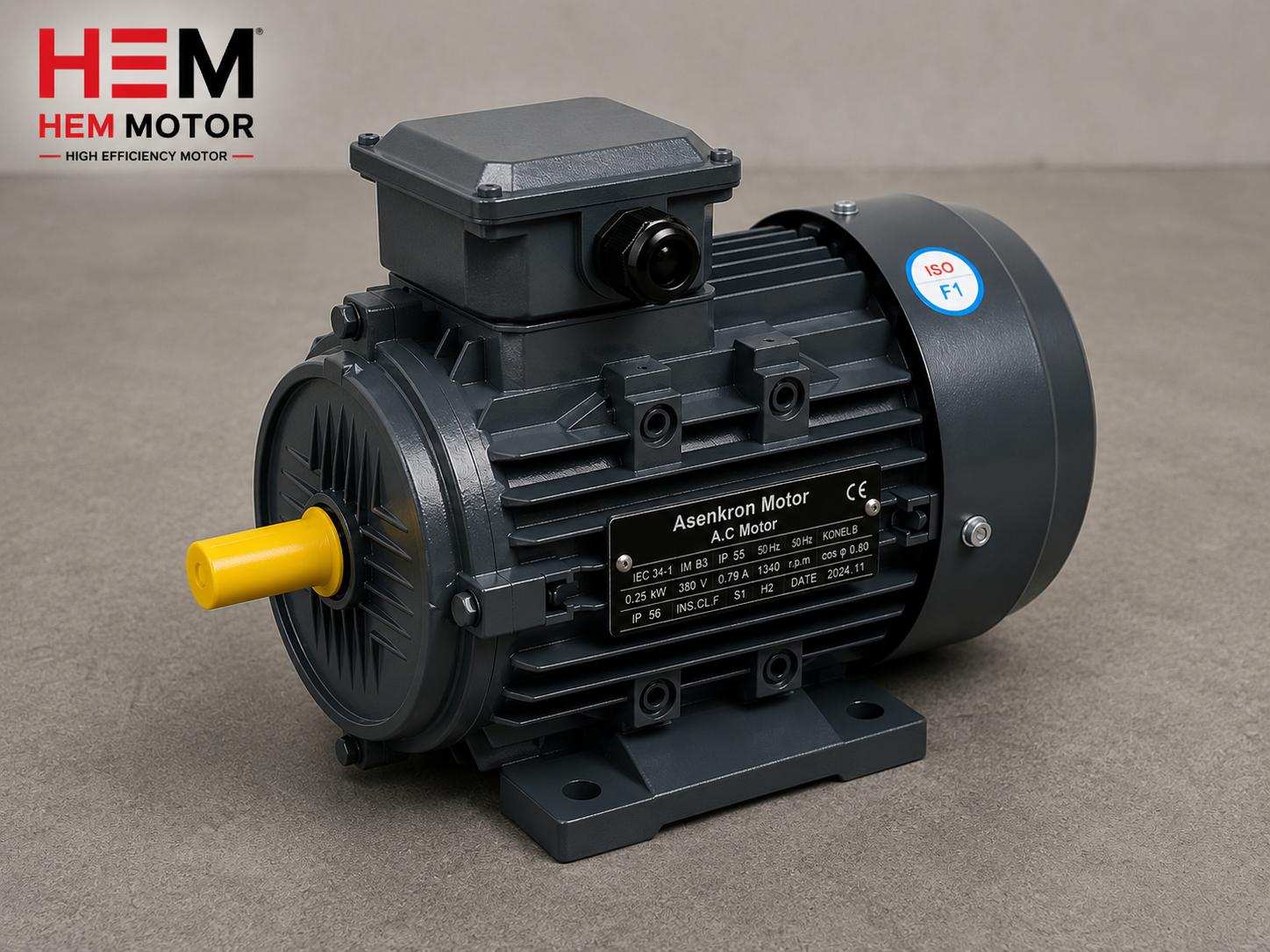
IE3 efficient electric motors have become standard in industry alongside energy efficiency regulations. However, even a high-efficiency motor draws reactive power from the grid that, if not managed correctly, comes back as a reactive penalty on the electricity bill. This is where power factor (cos φ) correction with capacitors and bank compensation come in. In this article we examine where reactive power originates in IE3 motors, the difference between motor-side (local) compensation and central bank compensation, and correct capacitor supply, from the perspective of an electric motor manufacturer and seller. To select the right IE3 motor, you can review our current electric motor prices and product range.
Reactive Power and cos φ: Where Does the Problem Arise?
To establish its magnetic field, an asynchronous motor draws reactive (inductive) power from the grid. This power does no work but loads the line, the transformer and the meter. The power factor (cos φ) shows how much of the total apparent power the motor draws from the grid is actually working active power. As cos φ falls, more current is drawn for the same work, and the distribution company applies a reactive penalty.
- Active power: The power doing work at the motor shaft, measured in kW.
- Reactive power: The power establishing the magnetic field, measured in kVAr, doing no work.
- Power factor (cos φ): The ratio of active power to apparent power; the closer to 1, the better.
Although IE3 motors are highly efficient, their power factor can drop especially at partial load, because the magnetizing current remains largely constant even as load decreases. Therefore, in motors running at partial load the reactive draw rises proportionally.
Motor-Side (Local) Compensation
Motor-side compensation means connecting the capacitor directly to the motor terminals or very close to them. In this method the capacitor switches in and out together with the motor, meeting the motor's reactive demand at the source.
- Advantage: Reactive power is produced next to the motor, relieving the line and transformer; it needs no separate contactor.
- Correct sizing: The capacitor must be selected so it does not exceed the motor's no-load (magnetizing) reactive power; an oversized capacitor can cause self-excitation and overvoltage when the motor is switched off.
- Caution: In motors with a variable frequency drive (VFD), a capacitor is not connected directly to the motor terminals; placing a capacitor on the drive output damages the drive.
For motor-side capacitor selection and terminal connection, our article on terminal compensation capacitor on pump and fan motors offers a practical framework. On the IE4 side, for kVAr calculation and sizing, our guide on reactive power compensation and capacitor selection on IE4 motors is complementary.
Bank (Central) Compensation
Bank compensation meets the reactive demand of many motors in a facility from a central compensation panel, using stepped capacitor groups (banks) that switch in automatically. A reactive power control relay measures the instantaneous power factor and switches in as many steps as needed.
- Advantage: Provides balanced correction from a single point under the variable load of many motors; the capacitors are used more efficiently.
- Automatic control: The reactive control relay adds/removes steps as the load changes and holds the target cos φ.
- Harmonics: In facilities with heavy drive and rectifier loads, a capacitor + reactor (detuned) bank should be preferred; otherwise there is a risk of resonance and capacitor damage.
Which method is suitable depends on the facility's load profile and the operating regime of the motors. If there are many motors running under continuous and variable load, bank compensation stands out; for a single large, continuously running motor, motor-side compensation is preferable. The two can also be used together (hybrid).
Reactive Penalty and Bill Impact
Distribution companies penalize inductive reactive energy drawn and capacitive reactive energy fed back beyond certain limits. The aim of compensation is to keep the power factor on the safe side of the penalty threshold. However, over-compensation (excess capacitors) can push the system to the capacitive side at low load and cause a capacitive penalty; this is why automatic control is important.
- If the inductive limit is exceeded, an inductive reactive penalty is incurred.
- Over-compensation can cause a capacitive penalty at low load.
- Automatic stepped control maintains the correct cos φ as the load changes.
We covered the bill impact of the reactive penalty and the limits in detail in our article on reactive energy penalty and bill impact on efficient motors. For partial-load reactive draw and capacitor selection, our guide on power factor correction and capacitor selection on asynchronous motors is complementary.
Capacitor Sizing: How Much kVAr Is Needed?
The heart of compensation is correctly calculating how much reactive power (kVAr) to add. Too few capacitors do not prevent the penalty; too many capacitors cause a shift to the capacitive side at low load and a capacitive penalty. The sizing logic is as follows:
- Current power factor: The facility's or motor's current cos φ value is measured.
- Target power factor: A target is set on the safe side of the penalty threshold.
- Required kVAr: While active power stays constant, the reactive power needed for the difference between the current and target power factor is calculated.
- Motor-side limit: In local compensation, the capacitor must not exceed the motor's no-load magnetizing reactive power.
The critical rule in motor-side compensation is that the capacitor must not cause self-excitation when the motor is switched off. Therefore the capacitor is selected slightly below the reactive power the motor draws at no load. In bank compensation, the reactive control relay measures the load and adds/removes steps automatically, so this risk is managed. We covered motor-side kVAr calculation on the IE4 side in our article on power factor and partial-load reactive draw on IE4 motors.
Partial Load: Where Reactive Draw Increases Most
The most important point businesses overlook is that motors often run at partial load, not full load. When a motor runs below its rated power, its efficiency drops somewhat, but the real problem occurs in the power factor: because the magnetizing current stays largely constant, the share of active power falls as load decreases and cos φ regresses seriously.
- Over-sized motors run continuously at partial load and produce a poor power factor.
- Reactive draw rises proportionally at partial load; the reactive penalty risk increases.
- Selecting a motor at the correct power reduces the compensation need from the start.
Therefore, when making a compensation plan, the motor's real operating load must be considered. For terminal compensation and reactive power management in variable-load applications such as pumps and fans, our article on power factor and compensation on pump and fan motors offers a practical framework.
Harmonics and the Detuned (Reactor) Bank
In modern facilities, variable frequency drives, rectifiers and other non-linear loads inject harmonic currents into the grid. An ordinary compensation capacitor can resonate with these harmonics, draw excess current and be damaged in a short time. Therefore special precautions are needed in facilities with high harmonic loads:
- Detuned (reactor) bank: A reactor connected in series with the capacitor moves the resonance frequency away from the harmonics and protects the capacitor.
- Harmonic measurement: The facility's harmonic profile is measured and the appropriate bank type is selected.
- Filter: At high harmonic levels, active/passive filters are evaluated.
To see the reactive penalty and bill impact holistically, our article on power factor and reactive penalty on efficient motors offers a complementary view.
Correct Supply: IE3 Motor and Compensation Compatibility
As an electric motor manufacturer and seller, we recommend evaluating the motor together with the compensation strategy:
- The cos φ value on the motor nameplate is the first data point to anticipate the compensation need.
- In motors that will run at partial load, the reactive draw is more pronounced; the compensation plan should be made accordingly.
- In VFD applications a motor-side capacitor is not used; correction is done at the drive input and/or in the central panel.
- Moving from IE3 to IE4 increases efficiency but does not eliminate reactive power entirely; compensation may still be needed.
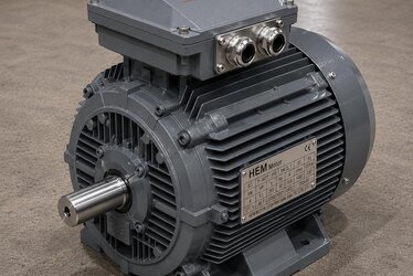
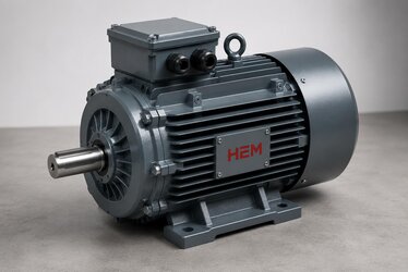
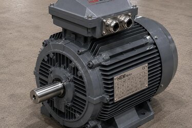
In the HEM Motor IE3 and IE4 product range, motors with clear nameplate values and suitable for compensation planning can be delivered quickly from stock.
Maintenance and Lifetime of Compensation Equipment
A compensation system is not equipment to be installed once and forgotten. Capacitors lose capacitance over time, contactor contacts wear, and the reactive control relay can begin to select the wrong step. A compensation panel left without maintenance can unknowingly push the facility outside the penalty threshold. The main points to watch are:
- Capacitor capacitance loss: The kVAr value of capacitors falls over time; periodic measurement confirms the target power factor is maintained.
- Step contactors: The contacts of compensation contactors that switch in and out frequently wear and may need replacement.
- Reactive control relay setting: The target power factor and step sequence must be set correctly; if the facility load has changed, they should be reviewed.
- Temperature and ventilation: Capacitors are affected by heat; panel ventilation directly affects capacitor life.
Regular maintenance both prevents the reactive penalty and extends the life of the compensation investment. When the motor and compensation are planned together, the facility's energy cost falls noticeably in the long term.
The Effect of Moving from IE3 to IE4 on Reactive Power
As the efficiency class rises (from IE3 to IE4), the motor's active power loss decreases; however, the power factor picture varies from application to application. Some businesses think they will be free of the reactive penalty when moving to IE4; yet reactive power arises from the motor's need for a magnetic field, independent of efficiency.
- IE4 motors run with slightly lower active power loss from the grid for the same shaft power.
- The power factor depends on the motor's load condition and design; the efficiency class alone does not end the penalty.
- Managing both efficiency and power factor together provides real energy savings.
Therefore the compensation plan should also be reviewed along with the efficiency class upgrade. Correct power factor management in IE3 and IE4 motors provides both regulatory compliance and bill savings together.
Frequently Asked Questions
Can I connect a capacitor directly to the IE3 motor terminals?
On a direct-on-line (DOL) IE3 motor, a correctly sized capacitor can be connected to the terminals or very close to them; this is motor-side compensation. However, the capacitor must not exceed the motor's no-load magnetizing reactive power; an oversized capacitor causes self-excitation and overvoltage when the motor is switched off. On motors with a variable frequency drive, a capacitor is not connected directly to the motor output.
Should I choose motor-side or bank compensation?
For a single large, continuously running motor, motor-side compensation is advantageous because it meets reactive power at the source. If there are many motors running under variable load, automatic stepped bank compensation is more flexible and efficient. In many facilities the two are used together (hybrid).
Does the reactive penalty end when I switch to an IE3 motor?
No. IE3 (and IE4) motors increase active power efficiency, but the motor still draws reactive power to establish its magnetic field. The power factor can drop especially at partial load. To avoid the reactive penalty, a correct compensation plan is needed regardless of the efficiency class.