English
 Türkçe
Summary (TL;DR)
- Power factor (cos φ) and efficiency are not the same thing: efficiency classes such as IE3 and IE4 define the motor's active power loss, not cos φ directly. A higher IE class does not automatically mean a higher power factor.
- An induction motor draws a magnetizing (reactive) current to establish the rotor field; this current delivers no shaft work but loads cables and transformers and can trigger utility reactive-energy penalties.
- At partial load, power factor collapses far faster than efficiency. Because the magnetizing current stays roughly constant regardless of load, at 25-50% load cos φ can drop to 0.5-0.6 or lower.
- An IE4 motor keeps its efficiency curve flatter at partial load, yet cos φ still falls. That is why correct kW sizing and, where needed, reactive compensation are critical.
- For a correctly sized IE4 motor from stock or fast supply, see electric motor prices and quotation support at HEM Motor; oversizing creates reactive penalties and loss cost.
When buying an electric motor, most people look only at the efficiency class on the nameplate (IE3, IE4) and the rated power. Yet a second quantity drives the plant's electricity bill, cable sizing, transformer loading and very often the reactive-energy penalty: the power factor, or cos φ. In this article we explain how power factor behaves in IE4 motors versus IE3, why reactive draw explodes at partial load, and how to choose the correct compensation, in engineering terms but with a clarity that turns into a sound purchasing decision. Our goal is to help you select the right IE4 motor at the right power and cut your plant's hidden reactive costs.

What Is Power Factor (cos φ) and Why It Differs From Efficiency
Power factor is the ratio of active power (kW) to apparent power (kVA). The total current drawn from the grid splits into two components: the active component delivered to the shaft as useful work, and the reactive component that builds and collapses the magnetic field. It is expressed as cos φ = kW / kVA and ranges between 0 and 1. The closer cos φ is to 1, the larger the share of the drawn current that does real work.
Efficiency is something entirely different. Efficiency is the ratio of mechanical power delivered to the shaft to the active power drawn from the grid. In other words, efficiency measures the power lost inside the motor as heat (copper losses, iron losses, friction and windage, stray load losses). The IE3 and IE4 classes grade these losses, not the power factor.
This distinction matters because a common field misconception says: "I bought IE4, so my power factor will improve too." That is not true. While a motor's active loss decreases (efficiency rises), its magnetizing requirement can stay the same depending on design, and in some IE4 designs that use more copper and a wider magnetic cross-section, full-load cos φ can even be slightly lower than the equivalent IE3. So efficiency going up does not pull power factor up by itself.
Where Does the Reactive Current Come From?
An asynchronous (induction) motor must apply a magnetizing current to the stator to create the rotating magnetic field. Unlike permanent-magnet synchronous machines, the induction motor's rotor field is fed by reactive current drawn from the grid. This current establishes the magnetic field in the windings, stores energy in the field during one cycle and returns it the next; on balance it delivers no shaft work. Yet it flows as real current in the cable, switchgear and transformer, contributing to I²R losses and voltage drop. That is exactly why a low cos φ fills up your plant's infrastructure while producing no useful work.
Is There a Power Factor Difference Between IE4 and IE3?
Short answer: there is no direct, guaranteed difference; the difference depends on the design. IE4 motors are optimized to cut losses: lower-loss electrical steel (thin laminations, low core loss), more and better-placed copper (lower I²R), improved slot geometry and a more efficient fan design. All of these reduce active loss and therefore raise efficiency.
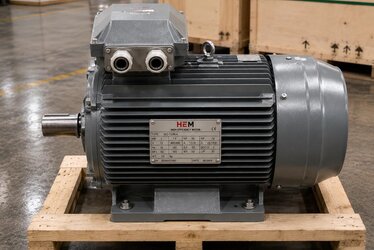
For power factor, the outcome varies with the design. In some IE4 designs the wider magnetic circuit can slightly increase the magnetizing current and pull full-load cos φ down a few percentage points versus the equivalent IE3. In other designs it is nearly identical. The key point is this: when buying IE4, do not assume cos φ improvement; evaluate the nameplate cos φ value and especially the partial-load behavior separately. For nameplate reading, reading kW, speed, cosφ and efficiency on an IE3 motor nameplate is a useful starting point; the same logic applies to IE4 nameplates.
IE4's Real Advantage: A Flat Efficiency Curve at Partial Load
The true strength of an IE4 motor is not in power factor but in holding its efficiency at partial load. A standard motor's efficiency curve peaks around 75-100% load and falls at light load. In IE4 motors this curve is flatter, so efficiency stays high even at 50-75% load. For variable-load applications (pumps, fans, compressors) this means significant energy savings. But this flat efficiency curve does not mean the power factor stays flat too; cos φ still drops at light load.
The Real Issue: Reactive Draw Exploding at Partial Load
This is the technical heart of the article. An induction motor's magnetizing current is essentially constant, independent of load. Whether the motor spins unloaded or at full load, it draws roughly the same reactive current to build the magnetic field. The active current, by contrast, varies in proportion to load: as load rises the active component grows, as load falls it shrinks.
The result is mathematically inevitable. At full load the active current is large, so the constant reactive component is a small fraction of total current and cos φ is high (for example 0.85-0.88). Drop the load to 25-50% and the active current shrinks while the reactive current stays the same, so the reactive share of total current grows and cos φ can collapse to 0.5-0.6 or even lower. The motor delivers very little shaft work while drawing a disproportionately large reactive load from the grid.
The practical meaning is this: an oversized motor (chosen larger than needed) always runs at partial load and continuously operates at poor power factor, generating hidden reactive cost. Many plants buy a motor a size or two larger "just in case"; the result is a higher purchase cost plus a permanent reactive penalty and extra cable/transformer loading.
Why Does cos φ Drop Even When Efficiency Does Not?
Even though an IE4 motor holds efficiency well at partial load, the magnetizing current does not change, by physics. Efficiency concerns the ratio of loss to active power, and in IE4 the losses are already low; but power factor concerns the balance of reactive to active current, and at light load that balance is broken. So "my efficiency is not dropping, therefore there is no problem" is misleading: reactive draw rises at light load independently of the efficiency curve. For correct sizing, the IE4 motor partial and low load efficiency and correct sizing article offers complementary guidance.
Correct Sizing: The Most Profitable Purchasing Step
The cheapest way to protect both power factor and efficiency is not spending money but choosing the right kW. When you size the motor so it operates at 75-100% load at its real duty point, efficiency sits in the peak region and cos φ stays high. The steps:
- Calculate the actual shaft power demand of the driven machine; base it on the real operating point, not the rated nameplate figure.
- If the continuous load profile is low, one size smaller IE4 motor usually gives better cos φ and lower reactive draw.
- Do not ignore starting torque and speed/pole count; downsizing purely for cos φ can cause start-up problems.
- For variable-load applications, an IE4 motor with a variable frequency drive (VFD) is often the best solution for both efficiency and reactive management.
At HEM Motor, we help you choose the right IE4 kW, pole count and speed combination for your application's load profile. From the broad IE4 electric motors product category, with stock and fast-supply options, you can make a choice that prevents oversizing-related reactive costs from the start.
Reactive Compensation: The Correct Method and Dangerous Mistakes
Despite correct sizing, induction motor systems usually need power factor correction capacitors. Compensation produces reactive power as close to the load as possible, reducing the reactive current drawn from the grid. But applied incorrectly it can be both dangerous and harmful.
Individual (Motor-Terminal) Compensation
This connects the capacitor directly to the motor terminals. The advantage is that it produces reactive power right at the source and relieves the cable. But beware: never over-compensate. If the capacitor is sized larger than the motor's magnetizing requirement (typically about 90% of the no-load reactive power), then when the motor is disconnected and coasts down (coast-down) there is a risk of self-excitation with the capacitor. This can create dangerous overvoltages at the motor terminals and damage both motor and capacitor.
Central / Automatic Capacitor Bank
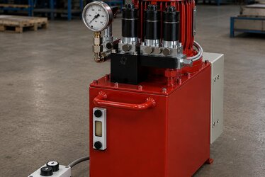
The most common solution in plants is an automatic (stepped) compensation panel at the main board. A reactive power controller measures the plant's instantaneous cos φ and switches steps in and out to hold the target power factor. In modern installations, detuned (reactor-equipped) steps are preferred against harmonic content; otherwise resonance and overcurrent can occur between harmonics and capacitors.
The Critical Rule for VFD-Fed Motors
This point is vital: never place a power factor correction capacitor between a VFD output and the motor. The drive's PWM output charges and discharges the capacitor at very high frequency, causing overcurrent, drive failure and capacitor rupture. And it is unnecessary anyway: the VFD's input stage (diode bridge or active front end) already keeps the displacement power factor close to 1. However, diode-bridge drives inject harmonic currents into the grid, which degrade the distortion power factor. In that case the solution is not a motor-terminal capacitor but a reactor/filter at the drive input and, if needed, detuned compensation on the panel side.
What to Watch When Buying
When purchasing an IE4 motor, power factor and total cost of ownership should be considered together. A practical checklist:
- Share the load profile: state what percentage load the motor will run at continuously; correct kW selection affects cos φ the most.
- Evaluate nameplate cos φ and efficiency together: they are different quantities; do not look at the IE class alone.
- State if a VFD will be used: with a drive-fed motor the compensation strategy changes completely.
- Ask about stock and lead time: stock availability matters so you do not wait for the right power; a quote with manufacturer assurance reduces delivery risk.
- Pole count and speed match: the same kW gives different cos φ and torque at different speeds; choose by application.
For current electric motor prices and an application-specific quote, simply send us your load profile; HEM Motor will evaluate the right IE4 motor together with a compensation recommendation.
Frequently Asked Questions
I bought an IE4 motor, will my power factor improve automatically?
No. The IE class defines efficiency (active loss), not power factor. An IE4 motor's full-load cos φ can be similar to, or sometimes a few points different from, the equivalent IE3 depending on design. To improve power factor you need correct sizing and, where required, compensation; raising the IE class alone is not enough.
If I choose a smaller motor, does cos φ really rise?
When you size the motor to run at 75-100% load at its real duty point, the active current becomes dominant over the reactive current and cos φ stays high. An oversized motor runs continuously at partial load and its cos φ can fall to 0.5-0.6. However, when downsizing you must also check starting torque and thermal capacity; the choice should not be made for cos φ alone.
Can I connect a capacitor to an IE4 motor running on a VFD?
No. A capacitor must never be placed between the drive output and the motor; it destroys both the drive and the capacitor. The drive's input stage already keeps the displacement power factor close to 1. To reduce harmonic-driven distortion, the solution is a reactor/filter at the drive input and, if needed, detuned compensation on the panel side.