English
 Türkçe
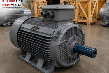
When ordering a cast iron electric motor, most buyers focus first on power and speed; yet the mounting position that defines how the motor attaches to the machine is just as critical. If the motor is to be fixed not to the floor but to a wall, a column or the ceiling, ordering a standard foot-mounted (B3) frame is often the wrong choice. This is exactly where the B6, B7 and B8 side and ceiling mounting positions come into play. In this article we cover, with a buying focus, what B6, B7 and B8 mean on cast iron motors, why terminal box orientation matters, how these positions affect lubrication and bearing life, and how to place a correct order. Our aim is to help everyone, from the machine builder to the maintenance manager, order the right position the first time.
Mounting position is coded according to the IEC 60034-7 standard and defines which surface the motor feet face and whether the shaft is horizontal or vertical. Thanks to their heavy mechanical strength, cast iron electric motors are far better suited to demanding positions such as side and ceiling mounting than aluminium frames. A motor ordered in the wrong position can leave the terminal box facing an inaccessible side, let condensation collect at the wrong point, and wear the bearings out earlier than expected. That means both lost time during commissioning and extra cost in the field.

Why State the Mounting Position at the Ordering Stage?
Many buyers think they can handle the mounting position by simply turning the motor in the field. While rotating the frame on a horizontal-shaft motor may seem possible, the terminal box direction, the location of the condensation drain holes and labelling for the correct position are matters that must be resolved at the factory. Forced field solutions both lower the protection class and put the warranty at risk. So in every project requiring side or ceiling mounting, the mounting position code must be stated clearly at the quotation stage.
What Exactly Are the B6, B7 and B8 Positions?
All three are essentially the foot-mounted (B3) frame fixed to a different surface; the shaft is always horizontal, and only the direction the feet face changes. For this reason they are usually derived from the same foot-mounted cast iron frame, but for correct operation the terminal box orientation and, in some cases, the lubrication arrangement differ. Below we explain each position, where it is preferred and what to watch for.
- B6 mounting position: The motor is mounted horizontally on a wall; the feet are on the wall side and, viewed from the shaft end, the motor leans to the left. It is preferred where floor space must be saved, and on conveyor or fan drives. It is common on belt-pulley systems running perpendicular to the wall.
- B7 mounting position: The mirror image of B6; the motor is again wall-mounted but, viewed from the shaft end, leans to the right. It is chosen when the layout requires the shaft and terminal box to face the opposite side. The choice between B6 and B7 often depends on whether there is clearance to the left or right of the mounting point.
- B8 mounting position: The motor is mounted to the ceiling, upside down; the feet are up, the body is down, and the shaft is horizontal. It is common on ventilation, extraction and ceiling-suspended conveyor systems. Because it saves floor space, it is a valuable solution in tight facilities.
Because the shaft stays horizontal in all of these positions, the basic bearing arrangement does not change; however, the body sitting in a different orientation in space directly affects cooling air flow, where condensation collects and the location of the drain holes. So the order should clearly state not only power and speed, but also the mounting position code.
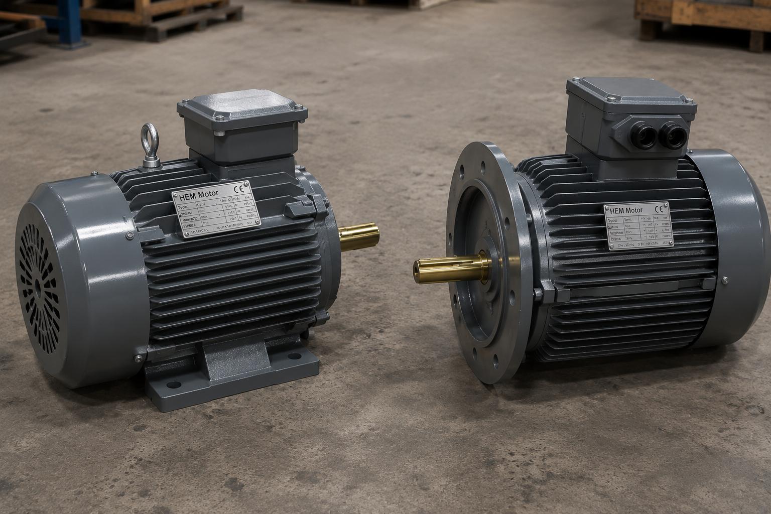
The Difference Between B3 and B6/B7/B8
In a B3 foot-mounted motor the motor sits on the floor with the feet pointing down. B6, B7 and B8 adapt the same foot-mounted frame to left-wall, right-wall and ceiling mounting respectively. Mechanically the frame is the same, but the manufacturer marks the motor according to the ordered position, because the nameplate notes, lubrication instructions and, where needed, bearing preload are defined for that position. For buyers who want fast delivery from stock, the most practical route is to source the foot-mounted cast iron frame and clarify the terminal and mounting details for the correct position with the manufacturer. This shortens the lead time and makes field mounting trouble-free.
Where They Sit Between Horizontal and Vertical Mounting
The B6, B7 and B8 positions belong to the horizontal-shaft group; that is, they do not require the axial load and special bearing arrangement of vertical mounting (V1, V3, V5, V6). This is an important advantage: the mechanical base of the standard horizontal motor is largely preserved, only the orientation of the body in space and the related details change. Therefore side and ceiling mounting is both more economical and easier to source from stock than vertical mounting.
Why Is Terminal Box Orientation So Important?
The most common problem in side and ceiling mounting is that the terminal box, where the cable is connected, arrives inaccessible or facing the wrong way. On a standard motor the terminal box is usually on top; but when the motor is mounted upside down in the B8 position, what we call the top now faces downward and the box may end up in a disadvantaged position with respect to oil, dust or condensation.
- Which way the terminal box will face after mounting must be stated at the ordering stage; on cast iron frames the box can usually be rotated and mounted in four different directions.
- Positioning the cable glands to face downward stops water running along the cable into the box and lets the IP55 protection actually work in the field.
- In ceiling (B8) mounting, enough clearance must be left to reach the box cover and connection bolts; otherwise future maintenance becomes seriously difficult.
- The terminal box direction also matters for future measurement and connection checks; a position where the technician can work comfortably should be chosen.
The correct terminal orientation determines both safety and ease of maintenance in the field. So when requesting a quote, stating in writing the mounting position together with the desired terminal/cable entry direction prevents wrong shipments. If a series of machines is being built, having all motors arrive with the same terminal orientation keeps the assembly line standardised.

Effect on Lubrication and Bearing Life
Because the shaft is horizontal, bearing lubrication in the B6, B7 and B8 positions is largely the same as in B3; this is one of the biggest advantages of these positions. Compared with vertical mounting (V1/V3), horizontal side and ceiling mounting distributes the axial load on the bearings more evenly. Still, there are points to watch:
- In ceiling mounting (B8) the motor is inverted, so any condensation drain holes in the fan cover and frame may no longer be at the lowest point; it must be confirmed with the manufacturer that these holes are open in the correct location.
- On large frames with re-greasing nipples, access to the grease inlet and the excess-grease outlet must remain possible after mounting.
- In continuously running (S1) applications, a cast iron frame distributes heat more steadily than aluminium, which is an advantage where cooling is somewhat restricted in side and ceiling mounting.
- In humid or outdoor applications, condensation can form inside the body when the motor stops; an anti-condensation heater option should be considered in these positions.
Bearing selection and the lubrication arrangement directly determine how many trouble-free hours the motor will run in the field. So in side and ceiling mounting, quality bearings and the correct grease type pay back far more than the initial investment.
Mind the Cooling and Air Flow
Motors are self-cooled by the fan at the rear (IC411). In side or ceiling mounting the air inlet grilles on the fan cover must be kept clear. If insufficient clearance is left between the fan cover and the surface on motors mounted close to a wall or ceiling, the motor overheats more than expected and efficiency drops. As a general rule, a distance allowing free air circulation must be kept between the fan cover and the nearest surface, depending on frame diameter. In ventilation and fan motor applications this rule is even more critical, since these motors often run in tight, hot spaces.
In ceiling mounting, because hot air rises, the zone where the motor works can be hotter than at floor level. In that case, power derating may be required for the ambient temperature; if a high ambient is expected, stating this at the quotation stage ensures the correct motor selection.
Which Position Is Preferred in Which Application?
The position choice depends largely on the machine layout and the available space. Common examples in practice are:
- On wall-mounted radial fans and extractors, B6 or B7 is usually preferred; keeping the terminal box on the accessible side is decisive.
- On ceiling-suspended conveyor and handling systems, B8 is common; this keeps the floor completely clear.
- In compact machine cabinets, where the motor must be fixed to a side wall, space is saved with B6/B7.
- In systems running with a gearbox, the mounting position of the gearbox and the position of the motor must be considered together.
Checklist for a Correct Order
To procure the right motor quickly and without error in an application requiring side or ceiling mounting, clarify the following before ordering:
- The required mounting position code: B6, B7 or B8 (left wall, right wall, ceiling).
- Frame material: cast iron frame for heavy duty and outdoor use.
- Power (kW), speed/pole number, frame size and shaft diameter.
- Terminal box and cable entry direction.
- Protection class (IP55 and above) and insulation class (F).
- Whether it will run continuously or intermittently (duty type) and the expected ambient temperature.
When this information is supplied in full, the motor marked in the correct position is prepared from stock or on a short lead time and needs no dismantling and rotation when it reaches the field. Choosing the correct mounting position on a manufacturer-backed motor both shortens the lead time and preserves the warranty scope. For current electric motor prices with different frame and mounting options, you can request a quote from the supply team.
Our guide on B5 vs B14 flanged motor mounting type selection is useful for those who want to compare flanged applications with side/ceiling mounting. To clarify frame size and power matching see our article on frame size and power matching in cast iron motors, and for the terminal and cable side, the motor terminal box and cable connection guide. You can also reach all our cast iron body motors content here.
Frequently Asked Questions
What is the difference between B6 and B7?
Both mount the motor horizontally on a wall; the difference is which way the motor leans when viewed from the shaft end. B6 leans left, B7 leans right. Which to choose depends on the shaft direction on the machine and the need to keep the terminal box on an accessible side.
Does ceiling mounting (B8) require a special motor?
In most cases the same foot-mounted cast iron frame is used; the critical difference is the correct positioning of the terminal box direction and the condensation drain holes for inverted mounting. It is enough to state the B8 position and the desired terminal orientation when ordering.
Does side mounting shorten bearing life?
As long as the shaft stays horizontal, the B6, B7 and B8 positions are very close to standard foot mounting in terms of bearing life. The real risk is poor cooling or inaccessible lubrication points; when these are planned correctly, side and ceiling mounting runs trouble-free for a long service life.