English
 Türkçe
In a drive system, the quantity the buyer actually needs is often not power (kW) but the output torque (Nm) at the shaft end and the output speed. The most robust way to select the correct motor power is to work backward from this output torque, arriving at the kW value through the gear ratio, efficiency and speed. In this guide we show step by step, using the relation P = T × n / 9550 with HEM Motor IE3/IE4 motors and worm-gear/bevel-helical reducers, how to make a correct and safe purchase.
The Core Relation: Power, Torque and Speed
The fundamental relationship underlying every electric motor selection is: P(kW) = T(Nm) × n(rpm) / 9550. Here the constant 9550 is the engineering constant that links the standard units (kW, Nm, rpm) together. This equation says power is proportional to both torque and speed: at the same power, as speed drops torque rises, and as speed rises torque falls. This is why, in applications requiring high torque at low speed, the motor alone is not enough; a reducer that lowers speed and multiplies torque by the ratio sits in between.
In practice the buyer first knows the output torque (Nm) and the desired output speed; the goal of the calculation is to work backward from these to the motor shaft and select the correct kW power and pole count. You can find a detailed application of power calculation for different load types such as pump, fan and conveyor in our Motor Power Calculation article.
Effect of Gear Ratio on Torque and Speed
A reducer does two things at once between the motor and the load: it lowers the speed and increases the torque. In the ideal (lossless) case the relationship is:
- Output speed = Motor speed / Ratio. For example, a 1500 rpm motor with a 1/30 ratio reducer gives 50 rpm output.
- Output torque = Motor torque × Ratio × Efficiency. Torque is multiplied by the ratio but reduced by the reducer efficiency (η).
- Output power = Input power × Efficiency. Power is conserved, reduced only by the efficiency loss; a reducer does not produce power, it converts it.
Therefore, when calculating motor kW from output torque, the required motor torque = output torque / (ratio × efficiency). Placing efficiency in the denominator, not the numerator, is a critical point; otherwise the motor is undersized and continuously strained. For the decision between a complete geared motor and a separate motor + reducer, our Geared Motor vs Separate comparison is a useful guide.
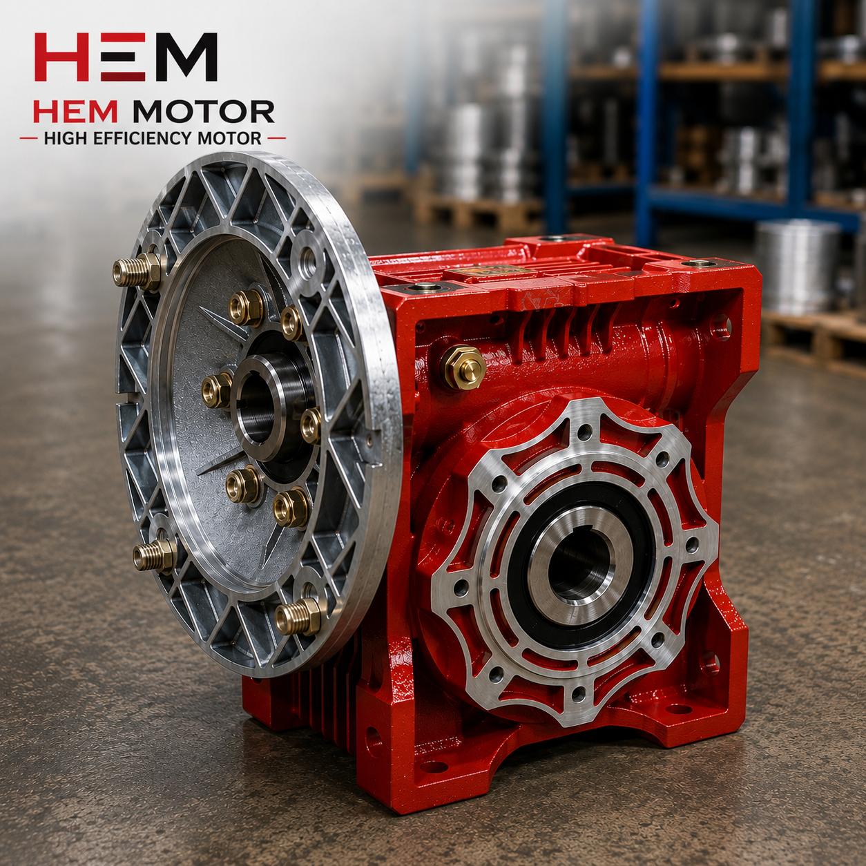
Worm-Gear vs Bevel-Helical Efficiency Difference
The reducer type directly determines the efficiency value entering the calculation. Worm-gear reducers (HEM30–HEM130, 1/7.5–1/100) offer a compact design, quiet operation and a right-angle drive advantage; their efficiency varies with the reduction ratio and can be lower especially at very high ratios. Bevel-helical (K-series) reducers generally offer higher efficiency and high torque capacity, so they are preferred in continuous heavy duty and at large powers. For the same output torque, a smaller motor may suffice with a bevel-helical reducer, while with a worm-gear the motor may be selected one step larger due to efficiency loss.
Selecting Base Speed with Pole Count
The rated speed of an asynchronous motor is set by its pole count: 2 poles ≈ 3000 rpm, 4 poles ≈ 1500 rpm, 6 poles ≈ 1000 rpm (synchronous values before slip on a 50 Hz supply). Since P = T × n / 9550, at the same power a lower-speed (6-pole) motor produces higher torque; this can reduce the gear ratio in some applications. Choosing the right base speed optimizes the gear ratio and thus cost and efficiency. For the effect of speed and torque characteristics on constant/variable loads, our Variable Speed Motor Selection article is helpful.
Step-by-Step Selection Example (Numerical)
Suppose a conveyor drive requires about 500 Nm output torque and 50 rpm output speed at the drive shaft. The output power is P = T × n / 9550 = 500 × 50 / 9550 ≈ 2.6 kW. To obtain 50 rpm from a 4-pole 1500 rpm motor, the gear ratio is 1500 / 50 = 1/30. Accounting for reducer efficiency, the motor power is found by dividing output power by efficiency; for example at 85% efficiency the required motor power is 2.6 / 0.85 ≈ 3.1 kW, which is safely met by a standard 4 kW IE3/IE4 motor.
In a second example, if a lower speed is needed, a 6-pole (1000 rpm) motor can be chosen so a smaller gear ratio is used for the same output speed; this rebalances the torque multiplier and the efficiency loss. The numbers given in these examples are standard engineering relations; in a real selection the load duty cycle, starting torque and service factor must always be added. For motor starting behavior and torque class, review our Asynchronous Motor Torque Classes article.
Service Factor and Safety Margin
The theoretical kW value found by calculation is not the motor to be purchased directly. A service factor and safety margin are added on top, because in real applications the starting torque, load fluctuations, temperature and continuous duty (S1) create extra demand. In general practice:
- Constant-torque loads (conveyor, hose pump, mixer) call for a generous safety margin.
- Variable-torque loads (centrifugal pump, fan) require the speed point to be chosen carefully since power changes rapidly with speed.
- In high starting-torque applications, the motor's torque class and inverter support are evaluated.
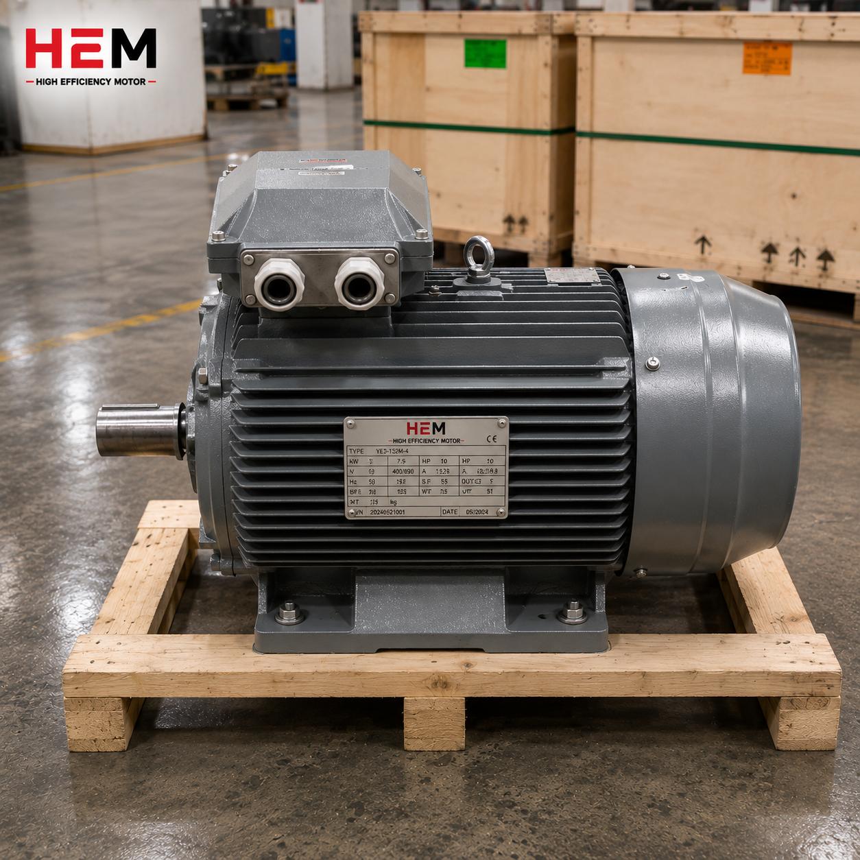
- In continuous S1 duty, Class F insulation, IP55 protection and 100% copper winding provide low losses and long life.
For the purchasing and selection details of a standard geared monoblock solution, our Monoblock Geared Motor article is a practical reference. For reducer-driven motor needs, you can select the appropriate power from our Reducer Electric Motors category.
Reading the Torque Profile Correctly by Load Type
When calculating power from output torque, it is necessary to evaluate not just a single instantaneous value but the torque profile of the load. This is because some loads show constant torque while others show speed-dependent variable torque, and this difference directly affects the selected motor power.
Constant-Torque Loads
Conveyors, mixers, hose pumps and lifting systems are constant-torque loads; the required torque is largely independent of speed. For these loads the output torque is determined directly, and the power calculated with P = T × n / 9550 varies linearly with the speed point. Where low speed is required, a 6-pole motor and a suitable gear ratio provide the required high torque efficiently.
Variable-Torque Loads
Centrifugal pumps and fans are variable-torque loads; the required power increases with the cube of speed. When working backward from output torque for these loads, it is critical to correctly choose the operating point (rated flow/pressure) at which the calculation is made. In variable-speed applications a frequency inverter adapts the power to the operating point, providing significant energy savings. You can find the distinction between the two load types in more detail in our Variable Speed Motor Selection article.
Common Mistakes in the Calculation
- Putting efficiency in the numerator: Reducer efficiency must always go in the denominator; otherwise the motor is undersized.
- Ignoring starting torque: A loaded start may require a peak value well above the rated torque.
- Forgetting slip: The real speed of an asynchronous motor under load is below the synchronous speed by the slip.
- Skipping the duty cycle: Continuous S1 load and intermittent load (S3) require different thermal sizing.
- Not adding a service factor: A safety margin for load fluctuation and temperature is essential.
Most of these mistakes lead to undersizing the motor and to early failure. For a correct selection, output torque, output speed, gear ratio, efficiency and duty cycle must be evaluated together.
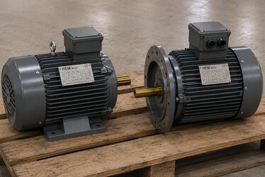
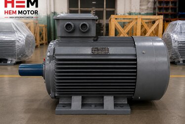
High-Power Motors and Mounting
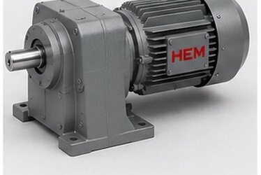
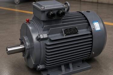
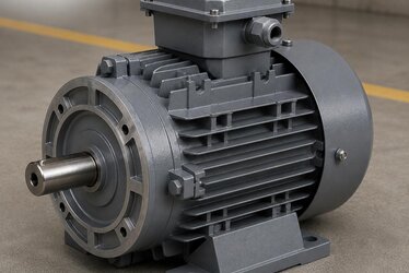
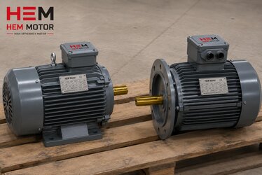
In heavy industrial applications where the calculation results in a large power, HEM Motor manufactures IE3/IE4 three-phase asynchronous motors up to 355 kW. These motors operate safely under continuous load with a cast iron body, Class F insulation and IP55 protection. For direct connection to the reducer, B5 or B35 flange mounting is preferred; this connects the motor shaft axially aligned with the reducer input shaft, reducing the need for an extra coupling. B3 foot-mounted and B14 small-flange options are also available for different interfaces.
To complete the correct torque-speed-power selection from stock, you can review our product groups and our general electric motor prices page. HEM Motor supplies the motor and reducer as a matched drive package, combining correct kW selection with ease of assembly.
Slip and the Effect of Real Output Speed on the Calculation
The synchronous speed printed on the motor nameplate (for example 1500 rpm) is not the same as the real speed the rotor turns under load; the difference is slip. At full load a 4-pole motor typically turns around 1440–1470 rpm. In dosing, filling or synchronized conveying applications where the output speed must be held precisely, these few percent appear directly at the reducer output. For that reason, using the loaded rated speed rather than the synchronous speed gives a more accurate result when you compute the output speed.
Slip also changes with load: as the motor is loaded the speed drops slightly while the output torque rises. This region of the torque-speed curve defines the motor's stable operating point. Where output-speed tolerance is critical, the speed is either held by a closed-loop variable frequency drive or accounted for in advance by choosing a safe motor step. Reading slip together with the load profile prevents surprises at commissioning.
Torque Units and Conversion Pitfalls
In the field, torque is sometimes given in kgf·m instead of Nm; 1 kgf·m is about 9.81 Nm. If the rated power is written in HP, use 1 HP ≈ 0.736 kW to convert to kW. Skipping these conversions can shift the calculation a full step to the wrong power. Therefore, before feeding torque, power and speed into the formula, make sure they are all in the same unit system. Working from a consistent table and applying P = T × n / 9550 with matching units largely removes the risk of buying the wrong power.
Positioning the Gear Ratio: Output Speed or Torque First?
In some applications the priority is to hit a specific output speed (for example a filling belt matching the line product speed), in others it is to guarantee a specific output torque (for example a loaded mixer not sticking on start-up). This priority drives the trade-off between gear ratio and motor pole count:
- Output-speed priority: Choose the ratio closest to the desired output speed, then verify the motor kW that satisfies the output torque.
- Output-torque priority: First convert the required torque to motor torque via ratio × efficiency, then pick the kW and pole count that supply it comfortably.
- Two-stage reduction: If a very low output speed is needed (e.g. below 10 rpm), consider a high-ratio worm gear or a multi-stage reducer instead of a single stage.
- Rounding to a standard step: When the calculation gives an intermediate kW, always step up to the next standard power for safety.
The wide ratio range from 1/7.5 to 1/100 across the HEM30–HEM130 worm-gear frames makes it possible to hit most output speeds in a single stage. For lines that demand high torque and continuous heavy duty, bevel-helical reducers deliver both higher efficiency and longer life. When you select the right ratio and the right motor kW together, the drive group is neither overstrained nor needlessly oversized and expensive.
Frequently Asked Questions
How do I calculate motor power from output torque?
First determine the output torque (Nm) and output speed (rpm), find the output power with P = T × n / 9550, then divide this power by the reducer efficiency to obtain the motor power. Determine the motor speed by pole count (1500/1000/3000 rpm) and the gear ratio (e.g. 1/30) based on the desired output speed. Finally add a safety margin for service factor and starting torque and round up to a standard kW step.
Why is reducer efficiency placed in the denominator?
A reducer does not produce power, it transmits it with loss. To obtain the output power the motor must provide more power, so required motor power = output power / efficiency. If you mistakenly put efficiency in the numerator you will undersize the motor and strain it continuously. Because bevel-helical reducers are generally more efficient, a smaller motor may suffice for the same output.
Why does a lower-speed motor of the same power give higher torque?
In the relation P = T × n / 9550, if power is constant, as speed (n) drops the torque (T) rises. Therefore a 6-pole (1000 rpm) motor produces higher rated torque than a 4-pole (1500 rpm) motor of the same kW. This lets you reduce the required gear ratio in some applications, achieving a more compact and efficient drive.