 English
 Türkçe
In industrial drives, reliability matters as much as efficiency when it comes to total cost of ownership. IE5 class synchronous reluctance motors combine high efficiency with long service life thanks to their magnet-free rotor design. Yet the path to realizing this potential in the field runs through a well-engineered temperature protection strategy. The single most critical variable governing the lifetime of an electric motor is the heat accumulating in its windings.
This article explains in detail how to combine PT100 sensors with the drive thermal model on IE5 SynRM motors, how overload protection logic works, how insulation lifetime relates to temperature, and how all of this should shape your procurement decisions. Our goal is to bring engineering reality and purchasing logic into the same frame.
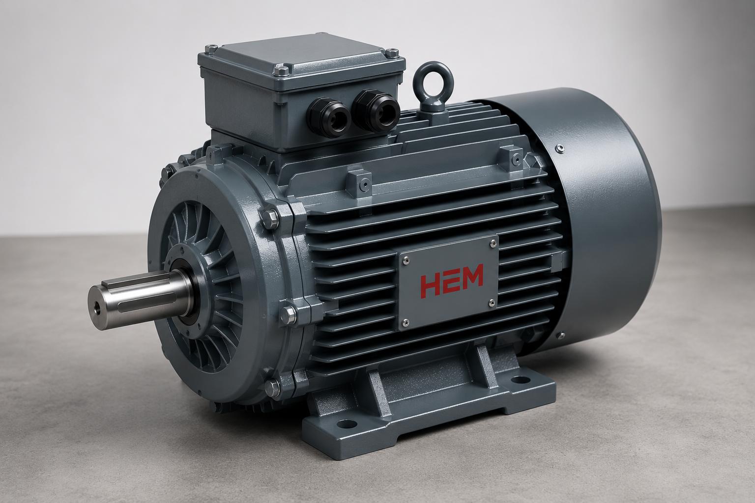
At HEM Motor, our cast-iron frame motors with IP55 protection, F class insulation and 100% copper windings are designed around this thermal protection philosophy across the 0.55 to 355 kW power range. Below you will find both the technical rationale and the practical implementation steps.
Why Is Heat So Critical on SynRM Motors?
Synchronous reluctance motors have no magnets on the rotor; torque is produced through the magnetic reluctance difference of the rotor. This eliminates magnet-related losses and demagnetization risk. However, the stator winding of a SynRM motor still heats up due to copper and iron losses, just like a conventional motor. So one must not fall into the trap of thinking "no magnets, therefore no heat problem."
A temperature rise in the stator winding accelerates the chemical aging of the insulation material. The widely used 10°C rule states that every sustained 10°C rise in winding temperature roughly halves the insulation lifetime. This simple but unforgiving rule sums up why temperature protection is a necessity rather than a luxury.
Another critical point is cooling. Because SynRM motors run with a drive, they operate across a wide speed range. The shaft-mounted fan may not produce sufficient airflow at low speeds. If high torque demand continues at low speed, the motor's own fan becomes inadequate and forced cooling (an external fan or independent cooling unit) must step in. This is especially critical in applications such as extruders, mixers and conveyors that demand high torque at low speed.
Direct Winding Temperature Measurement with PT100
The PT100 is a platinum-based RTD (resistance temperature detector) that shows 100 ohms of resistance at 0°C. As temperature rises, its resistance increases along a near-linear curve, making it ideal for precise and repeatable measurements. On IE5 motors, PT100 sensors are typically embedded in the winding slots of the three phases to capture the hottest spot. Usually three are placed, one per phase.
The greatest advantage of the PT100 is that it delivers the absolute temperature value as an analog signal. This lets the operator read the instantaneous winding temperature from the panel or through SCADA, build trend charts, and take action before thresholds are approached. In other words, the PT100 is a data source for both protection and predictive maintenance.
Threshold-Based Protection with PTC Thermistor
PTC type sensors from the thermistor family work on a different logic. A PTC thermistor shows low resistance up to a defined rated operating temperature; once that temperature is exceeded, its resistance rises suddenly and steeply. A trip relay detects this abrupt change and stops the motor. The PTC does not give an absolute value, but it conveys the "critical threshold exceeded" message extremely reliably and quickly.
The ideal protection architecture combines the two: PT100 for continuous monitoring and trend analysis, and the PTC thermistor as the last line of safety. While the PT100 manages early warning and alarm levels, the thermistor provides backup protection for the physical cut-off. For deeper insight on how winding temperature should be monitored, see our guide on motor temperature monitoring with PT100 and thermistor.
Drive Thermal Model: I²t and Calculated Protection
Alongside physical sensors, modern drives also run a mathematical motor thermal model. This model continuously measures the current going to the motor and computes a virtual temperature value using the I²t (current squared times time) principle. The drive thermal model uses the motor's thermal time constant, rated current and speed information to estimate how much the winding has heated up without needing a real sensor.
The power of this model lies in its ability to account for the reduction in cooling at lower speeds. For example, if the motor draws rated current at low speed, the cooling from its own fan weakens, so the drive thermal model automatically reduces the permitted continuous current. This is called "speed-dependent thermal derating" and is vital especially in SynRM applications.
When Sensor and Model Work Together
The most robust protection is achieved when the calculated model and real sensor data validate each other. The drive thermal model responds quickly and requires no extra wiring; the PT100 provides the real physical temperature. When the two work together, model drift is caught by the sensor and false positive/negative trips are minimized. For details on the thermal behavior and cooling strategies of IE5 SynRM motors, our article on IE5 synchronous reluctance motor thermal behavior and cooling is a comprehensive resource.
How Is Overload Protection Configured?
Overload protection is the mechanism that prevents the motor from running above its rated values for extended periods. On SynRM motors, this protection is performed not by a classic thermal overload relay but directly through the drive, since the motor never runs without a drive anyway. The drive feeds the current it measures into the motor thermal model and, when the threshold is crossed, first issues an alarm and then trips to a fault stop.
A well-configured overload strategy includes the following layers:
- Continuous operation limit: The load level that can be sustained indefinitely, determined by the motor's rated current and thermal time constant.
- Short-term overload window: Typically allowing 150% of rated current for a few seconds or tens of seconds; necessary for startup and transient torque demands.
- Speed-dependent derating: Automatic reduction of the continuous current limit at low speeds; this derating can be softened if forced cooling is present.
- Temperature threshold priority: If the PT100 or thermistor detects the critical temperature, the motor is stopped regardless of the current limit.
This layered approach both avoids triggering unnecessary production stoppages and protects the motor at moments of genuine danger. For step-by-step guidance on setting drive parameters, the IE5 synchronous reluctance motor drive parametering guide walks you through it.
Insulation Class, Temperature Class and Lifetime
HEM motors are manufactured with F class insulation. F insulation is designed to withstand a 105 K temperature rise (a total of 145°C, up to 155°C including the 10°C hot-spot allowance) assuming a 40°C ambient. However, good engineering practice is to design the motor to F class while operating it at a B class temperature rise (80 K). This "B temperature rise / F insulation" approach leaves a significant thermal reserve in the winding.
The value of this reserve margin is directly related to the 10°C rule mentioned above. A motor operating 25°C below its insulation class limit will, by the mathematics of the rule, have several times longer insulation life. This is precisely where continuous monitoring with the PT100 and drive thermal model becomes the tool that guarantees the motor stays within this safe window.
- F insulation: 155°C upper limit; offers a wide safety margin.
- B temperature rise operation: Keeps the winding away from the limit and extends life.
- Continuous temperature monitoring: Makes real operating temperature visible and prevents surprise failures.
- Forced cooling option: Preserves the thermal margin during low-speed continuous operation.
Commissioning and Autotune Steps
SynRM motors do not run without a drive; therefore the commissioning process begins with correctly matching motor and drive. The first step is entering the motor nameplate values (power, current, frequency, speed, winding connection) into the drive. Then the drive's autotune (automatic identification) function is run.
During autotune the drive measures the motor's stator resistance, axial inductances (Ld and Lq) and magnetic saturation characteristic. Since the Ld-Lq difference is the source of torque in SynRM motors, correct identification of these parameters is decisive for performance. A faulty autotune manifests as low torque, vibration or unnecessary heating.
The critical steps for thermal protection during commissioning are: correctly wiring the PT100 sensor channels to the drive or a separate monitoring relay, entering threshold and alarm temperatures in line with the insulation class, selecting the speed-dependent derating curve according to the application, and testing the operating logic of the forced cooling fan. For drive-installation compatibility and a commissioning checklist, our article on IE5 motor drive installation compatibility and commissioning offers a practical checkpoint.
Procurement and Purchasing Perspective
Thermal protection is not only an engineering matter but also a purchasing decision. The questions you should ask when procuring an IE5 SynRM motor directly affect the motor's total cost of ownership. Is the sensor hardware factory-integrated or added later? What insulation class is the motor? Are the drive and motor supplied from the same vendor as a compatible package?
Correct procurement requires evaluating the motor and drive as a whole. The efficiency advantage of the SynRM motor turns into real savings only when the motor is properly protected and long-lived. A motor with factory-integrated PT100, F insulation, IP55 protection and tested with its drive minimizes the surprises that can arise in the field.
The IE3, IE4 and IE5 motors in the HEM range are manufactured with 100% copper windings and cast-iron frames to meet this reliability expectation. To explore high-efficiency motor options and technical details, browse our High Efficiency Electric Motors category and find out about current electric motor prices.
Frequently Asked Questions
Since a SynRM motor has no magnets, is temperature protection really necessary?
Yes, absolutely. The absence of magnets on the rotor eliminates demagnetization risk, but the stator winding still heats up due to copper and iron losses. Insulation lifetime depends directly on winding temperature, and the 10°C rule states that every 10°C rise halves the life. For this reason, temperature protection with PT100 and the drive thermal model is indispensable on SynRM motors too.
Should I choose PT100 or the drive thermal model?
They are not alternatives but complements. The drive thermal model provides fast protection without extra wiring and manages speed-dependent derating; the PT100 delivers the real physical temperature as an analog signal and provides data for predictive maintenance. The safest setup uses both together so the model is validated by the sensor.
What should I do in applications requiring high torque at low speed?
The motor's own shaft fan produces insufficient airflow at low speed, so forced cooling (an independently supplied external fan) is recommended. In addition, the speed-dependent current limit in the drive thermal model must be set correctly and the PT100 thresholds defined according to the application. With forced cooling, the continuous current limit is preserved and the motor can run safely at full load even at low speed.


