English
 Türkçe
When buying an IE3 electric motor, the focus is usually on power, speed and frame size; yet the details that decide whether the motor is commissioned smoothly in the field are the terminal box, the cable gland and the cable cross-section selection. Even a correctly sized premium-efficiency motor cannot be put into service if the terminal box faces the wrong way relative to the panel, if the gland thread does not match the cable, or if the cross-section cannot carry the rated current; the IP protection is lost and returns occur. In this guide we cover, step by step, the construction of the terminal box in an IE3 motor, its connection arrangement, gland thread type and size matching, cable cross-section selection, and how all of this reflects on the order. The goal is to help you source the right product from the outset so the motor can be connected in a single attempt, error-free and with its IP55 protection preserved.
Terminal Box Construction and Purpose in an IE3 Motor
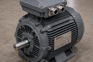
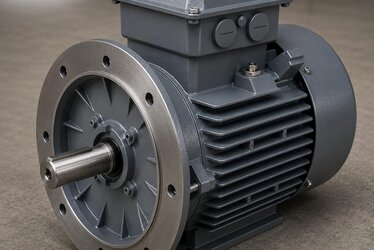
The terminal box is the sealed enclosure, seated tightly on the frame, where the motor's winding ends are connected to the external cable. In IE3 premium-efficiency motors the terminal box must be compatible with the motor's overall protection class; that is, if the motor is IP55, the terminal box must provide at least IP55 sealing. Otherwise the box becomes the weakest link in the system and the ingress of dust and water nullifies the protection of the entire motor. A well-designed terminal box contains the following:
- Terminal block: The carrier block, made of insulating material, where the six winding ends are connected.
- Gaskets (sealing gaskets): Elastomer gaskets between the cover and the box and between the box and the frame that provide IP protection.
- Cable entry holes: The threaded entries where glands are mounted.
- Earth terminal: The point inside the box and, on most motors, on the frame, where the yellow-green protective conductor is connected.
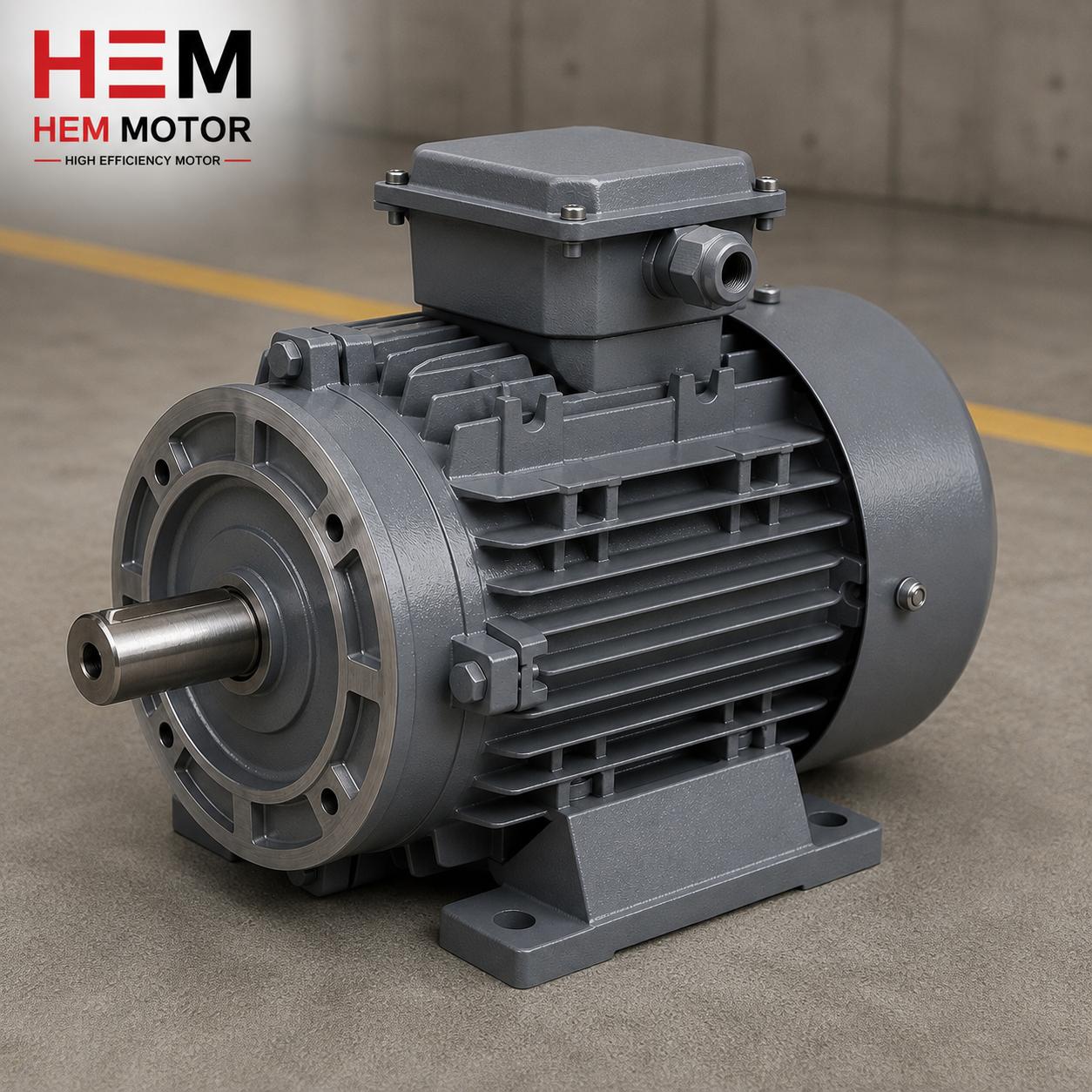
In cast-iron body IE3 motors the terminal box is usually cast as well, which increases mechanical strength and heat dissipation. In HEM Motor production, terminal boxes are offered ready with the entry directions and gland options most often needed in the field.
Terminal Block and Six-Lead Connection: Star and Delta Bridging
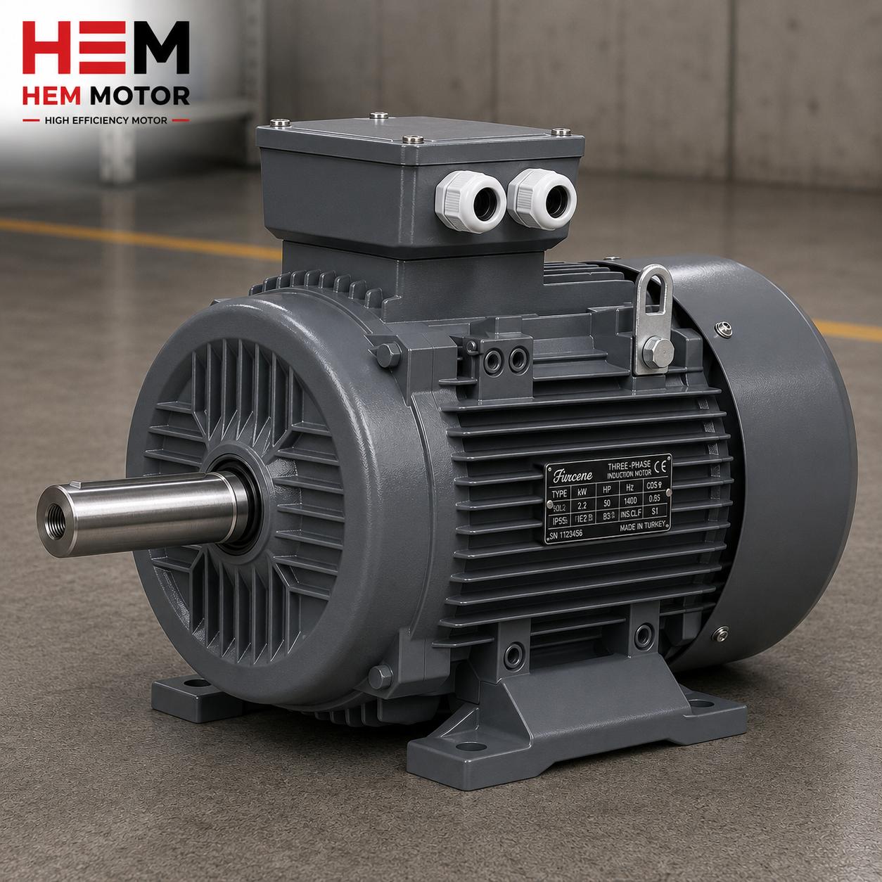
In three-phase asynchronous IE3 motors, the six winding ends come out to the terminal block: U1, V1, W1 and U2, V2, W2. These six ends are joined in different arrangements with bridge bars to connect the motor in star (Y) or delta (Δ). Which connection is chosen depends on the mains voltage and the voltage range stated on the motor nameplate:
- Delta (Δ) connection: At the lower voltage value (for example, if the nameplate states 400 V Δ), the bridges are fitted in the delta arrangement.
- Star (Y) connection: At the higher voltage value, the bridges are fitted in the star arrangement and the common point is joined.
Fitting the bridge bars correctly and tightening the terminal nuts to the correct torque is critical both for the motor to run at the right voltage and to prevent heating at the connection point. A loose terminal connection leads over time to arcing, blackening and phase loss. On connection quality and cable end preparation, our article on cable connection and cable lug selection is a complementary resource. For selecting cable and protection devices by rated current, see our IE3 rated current cable fuse contactor selection content.
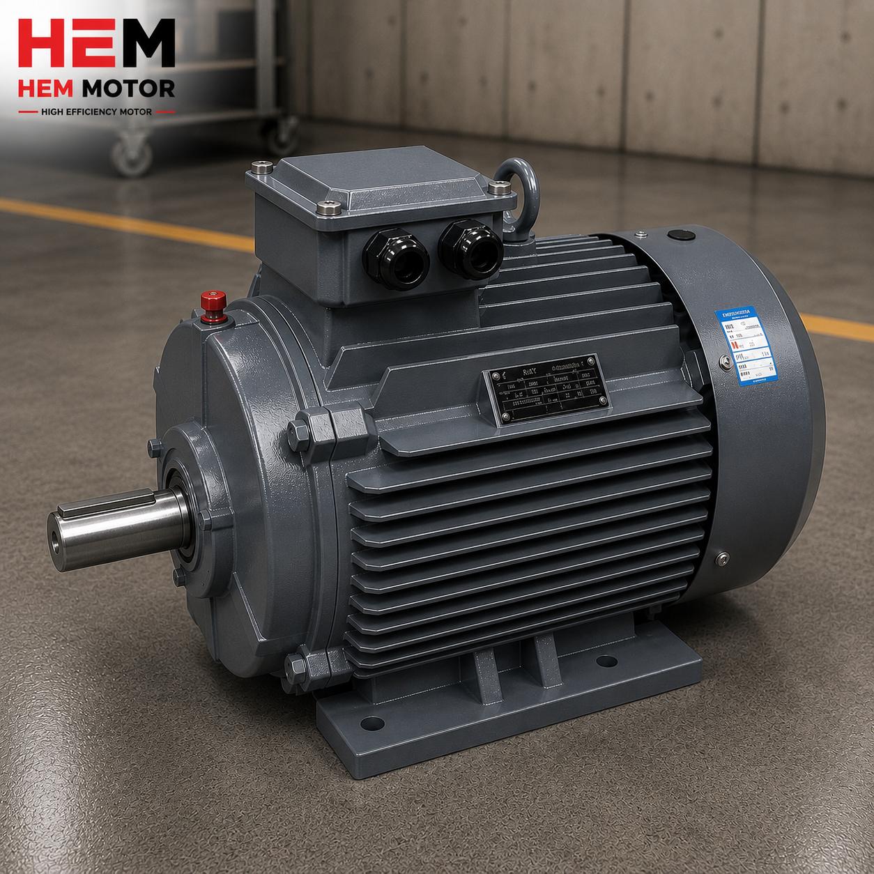
Cable Gland Selection: Thread Type and Size Matching
The cable gland is the fitting that provides both mechanical retention and sealing at the point where the cable enters the terminal box. There are two fundamental matches in gland selection: the thread type, and the suitability of the gland size to the cable outer diameter.
Thread Type: Metric, PG or NPT
The entry holes of the terminal box may be threaded to different standards. The most common is the metric (M) thread; alongside it, the older PG type and, especially in export projects, the NPT thread are used. The gland thread must match the box entry thread exactly; otherwise sealing cannot be achieved. You can find the detail of how the metric-versus-NPT distinction affects field orders in our cable gland metric or NPT guide.
Gland Size and Cable Outer Diameter
Each gland has a clamping range for a specific band of cable outer diameter. A thick cable will not enter too small a gland; in too large a gland, the sealing gasket cannot grip the cable enough and the IP protection is lost. The cable outer diameter must therefore be known in advance and the gland size selected accordingly.
- Brass (metal) gland: Durable, resistant to heat and mechanical stress; suitable for heavy industrial environments.
- Plastic (polyamide) gland: Light, corrosion-resistant, more economical; sufficient for standard applications.
- EMC gland: Used in drive-fed (VFD) systems to earth the screen of a screened cable through 360 degrees; it suppresses high-frequency interference.
Cable Cross-Section Selection: Rated Current, Voltage Drop and Installation Method
The cable cross-section must be selected to carry the motor's rated current safely. The cross-section is determined by three main criteria:
- Rated current (current-carrying capacity): The current the motor draws must stay below the permitted current of the chosen cross-section. An undersized cross-section causes the cable to overheat and shortens insulation life.
- Voltage drop: On long cable runs, if the cross-section is insufficient, the voltage reaching the motor terminal falls; the motor is strained and efficiency and torque decrease. On long lines the cross-section is increased by one step.
- Installation (laying) method: Whether the cable is laid in a trunking, in conduit, in air or buried changes the current-carrying capacity. In hot and confined environments the cross-section grows.
Although IE3 premium-efficiency motors run with lower losses at the same power thanks to 100% copper windings and high efficiency, the cable cross-section must always be calculated according to the motor's real rated current and field conditions. Fuse and contactor selection must be made coherently together with the cross-section.
Preserving IP Protection: Blanking Plugs and Earthing
There are two most common mistakes that break the terminal box's IP protection in the field. The first is leaving unused cable entry holes open. Every empty hole must be closed with a blanking plug together with its gasket; otherwise dust and moisture enter the box directly and the IP55 protection loses its meaning. The second is incorrect seating of the cover gasket or missing/loose cover bolts.
Earthing is critical for both safety and IP. The protective conductor (yellow-green) must be connected with the correct cross-section and firmly to the earth terminal inside the box or on the frame. In drive-fed systems, the use of screened cable and an EMC gland is recommended to prevent high-frequency bearing currents and EMC problems. Selecting the terminal box orientation and cable entry side correctly relative to the panel also eases commissioning; we cover this in our terminal box cable entry direction article.
How All This Affects the Order: Error-Free Field Buying
If the terminal box, gland and cross-section details are not determined correctly, the motor cannot be connected even when it arrives on site, and the project is delayed. The headings to clarify in the order are:
- The terminal box entry direction according to motor power, speed, frame size and connection arrangement.
- The gland count, thread type and size suited to the number and outer diameter of cables.
- The cable cross-section calculated for the rated current and distance.
- Blanking plugs for empty holes, and the need for an EMC gland in a drive-fed system.
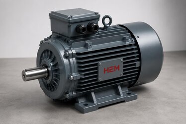
At HEM Motor we supply IE3 motors ready for the field, with the most needed terminal box entry directions and gland options. Across a wide power range from 0.55 kW to 355 kW, with cast-iron body and IP55 protection standard, we deliver from stock together with the correct cross-section and gland recommendation. For current elektrik motoru fiyatları and stock status, contact us and obtain, with manufacturer assurance, a motor that can be commissioned in a single attempt on your site.
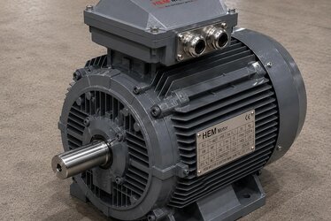
Terminal Box Size and How It Changes With the Power Range
In IE3 motors the size of the terminal box is directly proportional to the motor's power and therefore to the rated current. In small-power motors (around 0.55 kW, for example) the terminal box is compact, with a single thin cable entry and a small terminal block. As power grows and the current carried rises, both the cable cross-section and the cross-section of the connection bars increase; this mandates a wider terminal box and larger gland entries. In high-power motors (above 110 kW, for example) several parallel cables are usually used, so the terminal box is designed to host multiple gland entries. Points to watch by power range at ordering:
- Small powers (0.55–4 kW): usually a single cable entry, a compact terminal box, a small metric thread.
- Medium powers (5.5–45 kW): a thicker single cable or twin cables; a medium gland and a larger terminal block.
- High powers (55–355 kW): parallel cables, multiple gland entries, a wide terminal box and strong busbar connections.
Terminal box selection therefore cannot be considered independently of the motor's power; the right box must have the right number and size of gland entries. HEM Motor supplies motors ready for the field across the entire range from 0.55 kW to 355 kW, with a terminal box and gland configuration suited to the power.
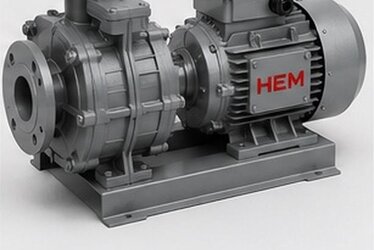
Terminal Block, Gland and Cross-Section in Drive-Fed (VFD) Systems
If the motor is driven by a variable-frequency drive, additional measures are required in terminal box and cable selection. Because the drive switches at high frequency, electromagnetic interference (EMC) and bearing currents can arise in the cable and at the motor terminal. To prevent these problems:
- Screened (shielded) cable must be used; the cable screen must be earthed through 360 degrees on the motor side.
- An EMC cable gland should be preferred to earth the screen correctly; a standard gland does not provide this function.
- The earth conductor cross-section must be chosen large enough to carry high-frequency currents.
- The cable cross-section should be set according to the voltage and current characteristics at the drive output, increased by one step where necessary.
In drive-fed systems, a second terminal group may also be needed inside the terminal box for a temperature sensor (PTC/Pt100) or heater connection. These options must be stated at the ordering stage; adding them later in the field is risky for both time and IP protection. HEM Motor offers motors suitable for VFD applications with drive-compatible winding insulation and EMC-suitable terminal solutions, under manufacturer assurance.
Commissioning Checklist in the Field
When the motor arrives on site, following a short checklist before the terminal box cover is opened and the connection is made largely prevents returns and failures:
- It is checked whether the voltage and connection information (Y/Δ) on the motor nameplate matches the mains voltage.
- It is examined whether the bridge bars on the terminal block are in the correct arrangement and the nuts are tightened to the correct torque.
- It is verified whether the outer diameter of the cable to be used fits the range of the cable gland to be fitted.
- It is checked whether all unused entries have gasketed blanking plugs fitted.
- It is checked whether the earth conductor is connected to the correct terminal with the correct cross-section.
- It is checked whether the cover gasket is seated properly and the cover bolts are tightened evenly to sufficient torque, so the IP55 protection is preserved.
When these steps are complete, the motor is commissioned on the first attempt without compromising its protection class. Sourcing the right motor with the correct terminal box and gland configuration from the outset is the shortest path to completing this list without trouble.
Frequently Asked Questions
Must I determine the IE3 motor's terminal box orientation before ordering?
Yes, because the side from which the cable comes to the motor from the panel is set by the orientation of the terminal box and its cable entry holes. If the direction is chosen correctly from the start, the motor connects with no field intervention. The wrong direction creates time-wasting solutions in the field such as turning the box or adding an elbow. HEM Motor offers motors from stock with the most-used entry directions.
What happens if I leave an empty cable entry hole open?
If every unused entry hole is not closed with a blanking plug, dust and moisture enter the terminal box directly. The motor's IP55 protection then becomes ineffective; moisture and corrosion at the winding ends create, over time, the risk of leakage and failure. Empty holes must always be fitted with a gasketed blanking plug.
Will there be a problem if I choose the cable cross-section smaller than required?
Yes. A cross-section below the rated current causes the cable to overheat, shortens insulation life and, on long runs, leads to voltage drop. When the voltage falls, the motor's torque and efficiency decrease and the winding is strained. The cross-section must be calculated according to the motor's rated current, the line length and the installation method, and increased by one step if necessary.