English
 Türkçe
Electric motors fed by a frequency drive (VFD) operate far more flexibly and energy-efficiently than fixed-speed grid supply. But this flexibility has a price: the high-frequency switching voltages produced by the VFD can create unwanted voltages on the motor shaft and therefore bearing currents. Over time these currents cause micro-erosion on the bearing balls and rolling surfaces, that is, EDM (electrical discharge machining)-like damage. Insulated bearings and shaft grounding on an IE3 motor are precisely the solutions that come into play to prevent this damage. In this article we address how bearing currents form, EDM damage and the correct supply strategy in VFD-fed motors.
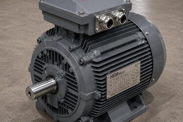
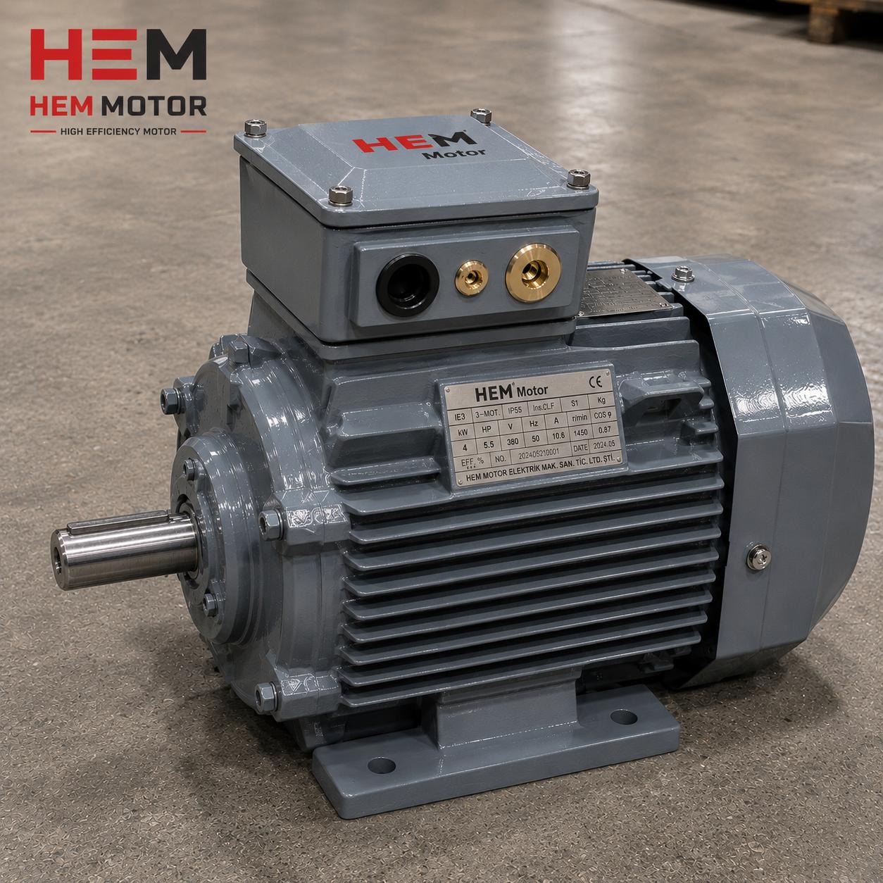
At HEM Motor, the IE3 and IE4 class motors we manufacture have robust insulation and quality bearing construction suitable for operation with a frequency drive. When supplying a motor to run with a VFD, not only power and speed but also bearing current protection must be planned from the outset. Otherwise the motor's bearings fail far earlier than expected and downtime cost arises.
How Do Bearing Currents Form?
A frequency drive switches the DC bus voltage at high speed to feed the motor. This switching creates, on average, a non-zero common mode voltage in the motor winding. This voltage reflects onto the shaft through the parasitic capacitances between the motor's stator and rotor, and a voltage builds up on the shaft. When the shaft voltage reaches a level that breaks through the bearing's oil film, a spark discharge (EDM) occurs and a microscopic crater forms on the bearing surface.
Although these discharges are individually very small, when the motor runs for thousands of hours, millions of discharges accumulate. As a result, a characteristic groove pattern (fluting) and noise appear on the bearing rolling surfaces. This is the root cause of early bearing failure in VFD-fed motors. This problem does not occur with standard grid supply; because in 50 Hz sinusoidal voltage there is no common mode voltage and no high-frequency switching.
In Which Motors Is the Risk Higher?
Bearing current risk increases as the motor frame grows larger. Generally, in larger-frame motors, the shaft and bearing dimensions are larger, so the parasitic capacitances and discharge energy rise. For this reason, in large-power VFD-fed motors, insulated bearings are almost a standard measure. In small frames the risk is lower, but the problem can also appear in small motors in applications with long cables and high switching frequency. We address the general factors affecting bearing life in detail in our bearing type and life in asynchronous motors article.
EDM Damage and Its Symptoms
EDM-induced bearing damage progresses in distinct stages. First micro-craters form, then these craters merge to create a groove pattern on the surface. At this stage the motor begins to make a characteristic humming or clicking sound. In the advanced stage the bearing clearance increases, vibration rises and finally the bearing seizes and stops the motor.
- Early symptom: An unexpected hum or high-frequency sound; especially noticeable in motors running with a VFD.
- Mid stage: Increased vibration, rising bearing temperature.
- Advanced stage: Bearing clearance, seizure and eventually mechanical failure.
EDM damage differs from standard bearing wear; the root cause is electrical, not mechanical. For this reason, merely replacing the bearing does not solve the problem; without cutting the bearing current path, the new bearing suffers the same damage. We address the impact of bearing failure on supply and downtime cost in our reducing motor failure and downtime cost article.
Types of Bearing Current and Their Effects
The bearing currents seen in VFD-fed motors do not arise from a single mechanism; several types of current act together. Understanding these is important for selecting the right protection solution. The most common type is the discharge (EDM) current, formed when the voltage accumulated on the shaft by the common mode voltage breaks through the oil film. This current damages the bearing surface as small but high-frequency pulses.
A second type is the circulating current. The high-frequency magnetic field creates a loop inside the motor body, and the current circulating in this loop passes through both bearings. This type of current is especially dominant in large-frame motors. A third type is the rotor grounding current; if the equipment on the load side is better grounded, the current on the shaft can flow toward the load side, damaging the bearings of both the motor and the connected equipment. Because each current type requires a different solution, the motor power and application details determine the protection strategy.
Which Current Type Requires Which Solution?
If the discharge current is dominant, the shaft grounding brush offers the most effective solution by discharging the current to ground before it reaches the bearing. If the circulating current is dominant, the bearing on the non-drive end must be insulated to cut the current loop; because insulation at a single point is enough to break the loop. In the case of rotor grounding current risk, both shaft grounding and load-side grounding must be set up in a balanced way. For this reason, when you share the motor's power, the drive type and the connection on the load side, we can determine the most suitable protection combination together.
Solutions: Insulated Bearings and Shaft Grounding
There are two basic ways to prevent bearing current: cut the current path (insulated bearing) or open a low-resistance alternative path for the current (shaft grounding brush). Usually these two methods are used together.
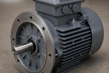
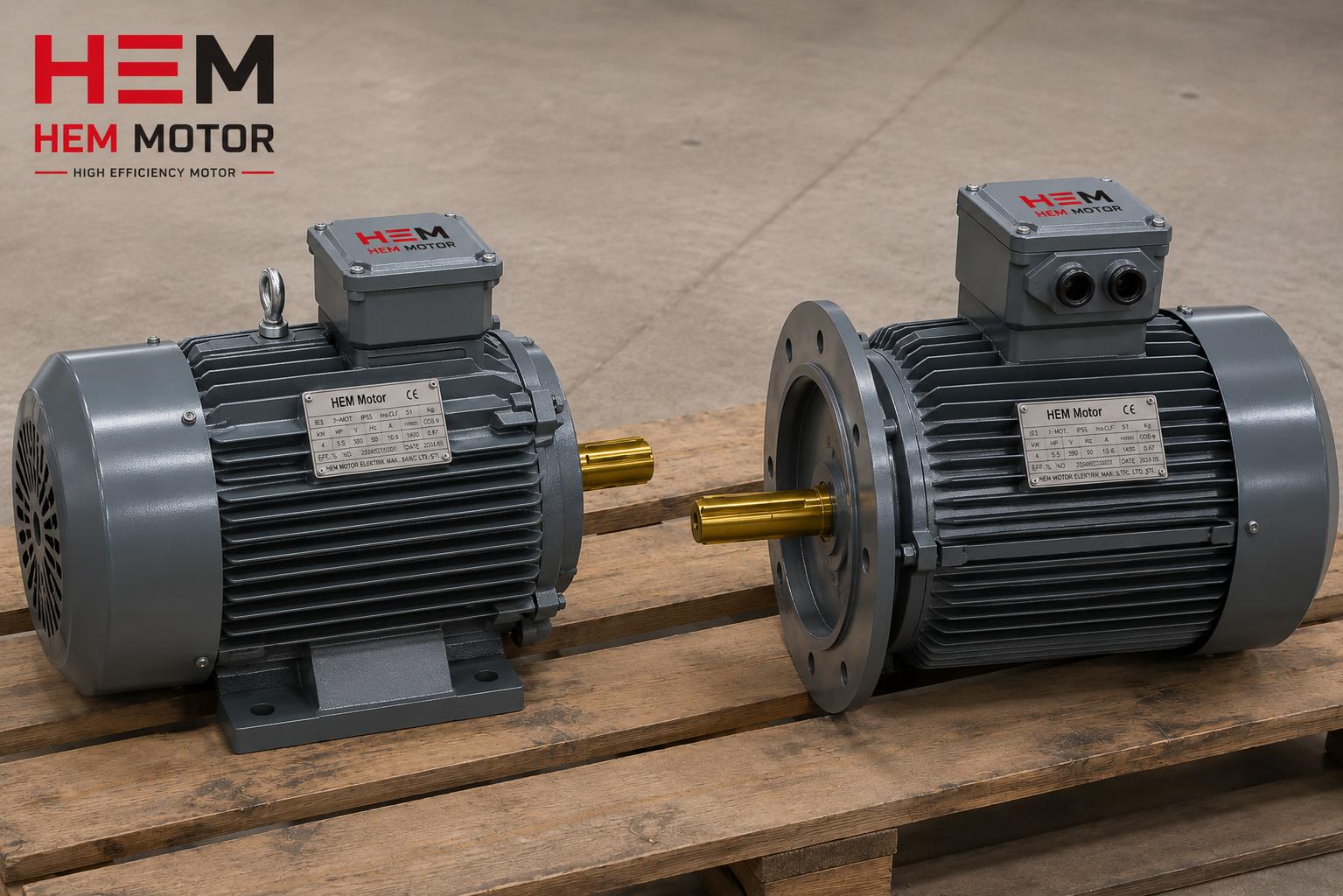
- Insulated bearing: An insulating coating applied to the bearing's outer ring or housing prevents the current from flowing through the bearing. It is generally applied to the non-drive (fan) end of the motor.
- Shaft grounding brush: Discharges the voltage on the shaft to ground before it reaches the bearing; thus the discharge energy flows through the brush instead of the bearing.
- Insulation at both ends: At high powers, insulation or combined solutions on both the drive and non-drive ends may be preferred.
- Correct cabling: Shielded motor cable and proper grounding reduce common mode voltage and therefore bearing current.
The right solution is determined by motor power, switching frequency and cable length. We address the general effects of VFD supply on the motor and the necessary measures comprehensively in our asynchronous motor with a frequency drive (VFD) article.
The Role of Cable Length and Switching Frequency
The severity of bearing current depends not only on the motor itself but also on the cable between the drive and the motor and on the drive's switching frequency. Long motor cables increase the capacitance along the line, raising the common mode current; moreover, in long cables, voltage peaks can form at the motor terminals due to voltage reflections. This strains both the winding insulation and the bearings. For this reason, in applications with long cables, using shielded motor cable and grounding the shield correctly at both ends is critically important.
As the switching frequency rises, the number of discharges per unit time increases; this means bearing damage accumulates faster. A high switching frequency can reduce the motor's noise and improve the current waveform, but it increases bearing current risk. This balance must be evaluated according to the application. When supplying the motor, sharing the drive's switching frequency and the cable length allows us to determine the right protection level.
Correct Supply Strategy for a VFD-Fed Motor
When supplying a motor to run with a VFD, specifying bearing current protection at the ordering stage is the healthiest approach. Replacing the bearing after buying the motor is both costly and time-consuming; whereas procuring a motor with insulated bearings from the factory ensures trouble-free commissioning in the field.
- Specify at the ordering stage: Clarify from the outset that it will run with a VFD and requires insulated bearings.
- Switching and cable information: The drive's switching frequency and the cable length between motor and drive determine the protection level.
- Efficiency and drive compatibility: IE3 and IE4 motors are suitable for operation with a drive; the right efficiency class also provides energy savings.
- Insulation strength: Under VFD supply, the winding insulation must withstand high dV/dt.
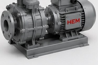
At HEM Motor we supply IE3 and IE4 class motors suitable for operation with a frequency drive, with insulated bearings on request. We quantify the energy gain of the high-efficiency motor and drive combination in pump-fan applications in our savings with high-efficiency motors and a frequency drive article. For current electric motor prices and stock status, our quotation process responds quickly. For our IE3 motor product family, see our IE3 efficient electric motors page.
Maintenance and Monitoring of VFD-Fed Motors
Even with the correct protection in place, periodic monitoring of VFD-fed motors extends their service life. Listening for early bearing noise, measuring bearing temperature and tracking vibration levels allow EDM-related damage to be caught before it becomes a failure. If a shaft grounding brush is used, the brush is a wear part and must be checked and replaced periodically; a worn brush loses its protective function and lets bearing currents flow again. Likewise, the grounding of shielded cables and the integrity of the grounding connections should be verified during maintenance, because a deteriorated grounding path raises common mode current. A simple, planned monitoring routine turns an invisible electrical problem into a manageable, predictable maintenance item.
Frequently Asked Questions
Does every VFD-fed motor need insulated bearings?
No, the need depends on motor power, switching frequency and cable length. Generally, in larger-frame motors the risk is high, so insulated bearings are almost a standard measure. In small-frame motors the risk is lower, but the problem can also appear in small motors in applications with long cables and high switching frequency. When you share the drive and cable information, we can determine the protection level suitable for your motor.
How is EDM damage recognised, and how does it differ from normal bearing wear?
The root cause of EDM damage is electrical, not mechanical; a characteristic groove pattern (fluting) forms on the bearing rolling surface, along with a hum noticeable in a motor running with a VFD. This is its difference from standard wear. For this reason, merely replacing the bearing does not solve the problem; a new bearing fitted without cutting the bearing current path suffers the same damage. The permanent solution is insulated bearings and/or shaft grounding.
Can I add insulated bearings later, or should I specify them at order?
The healthiest method is to specify at the ordering stage that the motor will run with a VFD and procure it with insulated bearings. Later bearing replacement is both costly and time-consuming, and makes it harder to plan the correct solution (insulation location, shaft grounding) according to field conditions. A motor that arrives with the correct protection from the factory is commissioned in the field smoothly and quickly.