English
 Türkçe
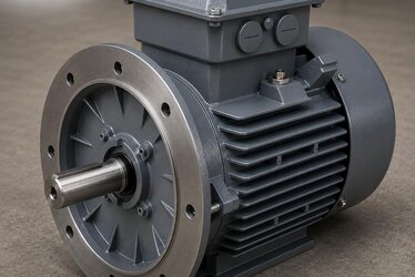
When ordering an IE3 electric motor, attention often narrows to a single heading: power and speed. Yet much of what determines whether the motor actually performs as expected on site comes down to the accessories fitted to the motor at the factory. Options such as the brake, encoder, forced cooling fan, PTC thermistor and counter-flange are not simple parts that can be bolted on and off afterwards; most of them directly affect the motor's mechanical design, shaft size, end-shield dimensions and terminal box layout. For this reason, these options must be defined at the order stage, before the motor leaves the production line.
In this article we examine the most frequently requested accessory options on IE3 efficiency-class asynchronous motors, explain which option is needed in which application, and show in technical detail how the wrong choice leads to rework, installation delays and downtime on site. Our aim is to clarify the questions you need to answer when filling out the order form, and to help you arrive at the right accessory combination so the motor runs the moment it is fitted. To quickly identify the right power, speed and frame before ordering, our IE3 electric motor stock guide is a good starting point.
Why Must Accessories Be Defined at the Order Stage?
On IE3 motors most accessories are produced as an integral part of the mechanical body. A brake motor, for example, is not a part simply screwed onto the back of a standard motor: the rear end-shield, the brake disc housing, the shaft length and sometimes the rotor balance change according to this option. Likewise, if an encoder is to be fitted, the motor's rear shaft end (non-drive end) and the encoder mounting flange must be prepared at the factory. If a forced cooling fan is to be added, a separately supplied fan unit replaces the standard fan cover, and an additional cable entry is planned for it.
Because of these structural dependencies, saying "let's add a brake too" after the motor arrives on site is practically impossible. Feedback from the field always points to the same conclusion: when a missing accessory is discovered, the motor is either sent back or forced into service with an incompatible workaround. Both outcomes waste time and money. Defining all of the application's requirements in advance at the order stage is therefore far more economical than any later intervention.
- Mechanical dependency: the brake, encoder and counter-flange affect the motor's shaft and end-shield dimensions.
- Electrical dependency: the forced fan, PTC and anti-condensation heater require additional cable entries and terminal arrangements.
- Lead-time impact: adding accessories to a standard from-stock motor can introduce extra time, similar to a production order.
- Warranty and compliance: factory-fitted accessories remain within the motor's overall warranty.
Brake Option: Torque and Load Holding
The brake is indispensable in vertical-axis hoisting applications, cranes, lifts, conveyor drives and systems requiring precise positioning. The most critical parameter when selecting a brake motor is the brake torque. The brake torque must be high enough to hold the load safely and to stop the system over a reasonable distance when required. Too little brake torque cannot hold the load; excessive brake torque can cause shock and wear in the mechanical system.
The brake type also varies with the application. The most common spring-applied DC brake engages automatically when power is lost, acting as a safety brake; this is a critical feature for hoisting applications. Whether the brake has a manual release lever, its supply voltage and the rectifier type are details that must also be clarified at the time of order. Where rapid stopping is required, a fast-release rectifier is preferred.
Questions to Ask When Selecting a Brake
- Is the application horizontal, or vertical/hoisting? A safety brake is essential in vertical use.
- What brake torque is required? The load moment and stopping time must be taken into account.
- Is a manual release lever needed? It is often requested for maintenance and emergencies.
- What is the brake supply voltage and rectifier type?
Encoder Option: Feedback and Position Accuracy
In applications where speed and position are precisely controlled, an encoder is fitted to the motor. The encoder feeds the rotational speed and angular position of the motor shaft back to the drive, enabling closed-loop control. In a vector-controlled drive or servo-like application, where high torque and precise positioning are demanded even at low speeds, the encoder becomes mandatory.
The main distinction in encoder selection is between incremental and absolute types. Incremental encoders count pulses; absolute encoders report the exact position at every instant and remove the need for a reference search after a power loss. Resolution (pulses per revolution), output type (HTL/TTL or SinCos) and supply voltage must be defined at the time of order. When selecting a motor to run with a frequency drive, our article on the VFD frequency drive with an asynchronous motor will help you establish the drive-motor compatibility correctly.
Forced Cooling Fan: Continuous Operation at Low Speed
A standard asynchronous motor cools itself with its own fan fitted to the shaft end. This method is adequate when the motor runs at its rated speed; however, if the motor is run for long periods at very low speeds via a frequency drive, the shaft-mounted fan also turns slowly and cooling becomes insufficient. In this case the motor temperature can rise to dangerous levels. The solution is the forced cooling fan.
The forced fan is a cooling unit driven by a separate electrical supply, independent of the motor's speed. Whether the motor turns at 5 Hz or at 50 Hz, the fan blows air at a constant speed and protects the thermal safety of the windings. In extruder, mixer, conveyor and pump applications running with variable load over a wide speed range, the forced fan is an investment that directly extends motor life. For motors with the forced fan option, the fan supply voltage (usually a separate small terminal) and fan rotation direction are also planned.
- Required for motors running for long periods at low speed over a wide speed range.
- Provides cooling at constant air flow, independent of motor speed.
- Often chosen together with a PTC thermistor for thermal safety.
PTC Thermistor and Thermal Protection
Protecting motor windings against overheating is critical to motor life. Standard thermal relays measure the external current but do not directly see the internal winding temperature. A PTC thermistor, embedded within the winding, senses the temperature directly and stops the motor via the drive or a protection relay when a set threshold is exceeded. Particularly in motors with forced fans or under heavy load, the PTC prevents unexpected winding burnouts.
Besides the PTC, some applications prefer a Pt100 temperature sensor to monitor the winding temperature continuously as an analog signal. Which sensor is needed depends on the motor's duty cycle and monitoring infrastructure. This too is an accessory decision to be made at the order stage.
Counter-Flange, Anti-Condensation Heater and Other Options
The counter-flange (B5 or B14 mounting) lets the motor connect directly by flange to a gearbox, pump or machine. The mounting arrangement (foot-mounted B3, flanged B5/B14 or combined B35) determines the motor's installation geometry and must be clarified at the time of order. In motors running in damp or intermittent service, an anti-condensation heater is added to prevent condensation in the winding during standstill. For motors operating outdoors, the protection class becomes important, and choosing a suitable IP protection class is a complementary decision.
Other frequently requested options include a second shaft end (double-ended shaft output), a special-size terminal box, terminal box orientation changes and special paint/protective coatings. Although each of these may seem like a small detail, together they form an integrated configuration that determines flawless operation of the motor on site.
Accessory Selection, Lead Time and Stock
Accessory decisions are not purely a technical matter; they also directly affect delivery time. While a standard IE3 motor can often be dispatched from stock the same day, options such as a brake, encoder or forced fan can extend the lead time when they require the motor to be specially configured. For this reason, in an urgent need it is important to separate early on which accessories are truly mandatory and which are optional. In some cases, applying a standard accessory package to a body held in stock shortens the time; in some special combinations, a production order becomes unavoidable.
Our approach is to anticipate frequently requested accessory combinations and keep them ready in stock, thereby minimising our customers' waiting time. For example, the common power and brake torque combinations of brake motors, the standard resolutions of encoder motors and forced-fan models are prioritised in stock planning. This way, a correctly accessorised motor can often be delivered without a long production wait.
Checklist for Ordering an Accessorised Motor
A practical checklist to review before ordering significantly reduces the margin for error and ensures a trouble-free first run on site:
- Mounting: Foot (B3), flange (B5/B14) or combined (B35) — which is required?
- Brake: Is it needed? What brake torque, manual release and supply voltage?
- Encoder: Incremental or absolute? What resolution and output type?
- Cooling: Is there long operation at low speed? Is a forced fan needed?
- Thermal protection: PTC, Pt100 or thermal switch — which is wanted?
- Environment: Damp, dust, outdoor? Is an IP class and anti-condensation heater required?
- Shaft: Single or double shaft end? Any special shaft size?
Each of these items is a decision that must be defined before the motor leaves the factory. When we review this configuration together, we also help you correctly interpret the rated values on the nameplate of the delivered motor.
The Right Accessory Combination: Trouble-Free First Run on Site
The ultimate goal in accessory selection is for the motor to run the moment it is fitted, with no extra intervention required when it arrives on site. To achieve this you must think about the application as a whole: is it hoisting, does it require precise positioning, does it run at low speed, is it in a dusty/damp environment? Each of these questions points to an accessory decision. For example, a closed-loop hoisting application most likely requires a brake, an encoder, a PTC and a forced fan all together.
When planning the balance between fast from-stock delivery and a custom accessorised configuration, our comparison of from-stock delivery versus production order makes the decision easier. With our wide motor stock and engineering support, you can contact us to define the brake torque, encoder resolution and cooling method suited to your application together, and have your motor delivered ready with the right accessory combination. You can reach all of our motor solutions from our homepage.
Frequently Asked Questions
Can I add a brake and encoder to an IE3 motor later?
It is not recommended in practice. The brake and encoder affect the motor's shaft length, rear end-shield structure and mounting flange, so they are prepared at the factory. Later intervention usually means incompatibility, loss of warranty and downtime. That is why these options must be defined at the order stage.
When does a forced cooling fan become mandatory?
A forced fan is needed if the motor will run for long periods at low speed via a frequency drive. At low speed the standard shaft-mounted fan cannot provide enough cooling and the winding temperature rises. The forced fan eliminates this risk with constant air flow independent of motor speed.
How should I determine the brake torque?
The brake torque is calculated from the moment of the load to be held and the required stopping performance. In hoisting applications a value that holds the load safely is chosen, while in horizontal applications a value that stops the system without shock is selected. If you share your application data, we can determine the correct brake torque together.