English
 Türkçe
Summary (TL;DR)
- The low-frequency hum you hear from an asynchronous motor usually comes not from the bearings but from the stator core; this sound is caused by magnetostriction.
- On a 50 Hz supply the magnetizing force varies with the square of the flux, so the tone appears at twice the line frequency -- at 100 Hz and its harmonics (200 Hz, 400 Hz). On a 60 Hz supply it is 120 Hz.
- Core noise is driven by silicon-steel grade, lamination tightness/impregnation, air-gap uniformity and body stiffness (cast iron damps low frequencies far better than thin aluminum).
- A VFD/PWM drive adds a carrier-frequency whine on top of the 100 Hz hum; raising the carrier frequency can push that tone beyond audibility.
- For quiet motor selection, look at the IEC 60034-9 sound power level Lw / dB(A), choose 6/8-pole low-speed designs, F insulation, IP55 and a cast iron body. HEM Motor targets quiet operation through manufacturing quality.
When you switch on a new motor, the steady, low-pitched hum that fills the room surprises many users: "Is the motor faulty, is a bearing damaged?" In most cases the answer is reassuring -- this sound is not a fault but an unavoidable consequence of physics. The most characteristic noise component in an asynchronous motor is the stator core hum produced by the magnetic field physically squeezing and releasing the lamination stack, that is, by magnetostriction. In this article we explain where this sound comes from, why it is heard exactly at 100 Hz, how to distinguish it from bearing and fan noise, and -- most importantly -- what to look for when buying a quieter motor.
What Is Stator Core Hum?
The stator of an asynchronous motor consists of copper windings placed on a magnetic core formed by stacking thin silicon-steel laminations. When voltage is applied, a rotating magnetic field passes through this core. That magnetic field deforms the steel at a microscopic level. In each cycle of the field the core first expands slightly, then contracts. Repeated hundreds of times per second, this dimensional change makes the lamination stack vibrate like a loudspeaker diaphragm and radiates into the air as sound. Most of the continuous buzz our ears perceive as "motor hum" is exactly this.
This vibration requires no mechanical contact (bearing, gear, fan); it is purely magnetic in origin. That is why this sound -- which you do not hear when turning the motor by hand -- appears the moment power is applied and continues even with no load, even while the motor freewheels. This is one of the most practical ways to diagnose the origin of the sound.
Magnetostriction: The Steel Breathing With the Field
Magnetostriction is the phenomenon by which ferromagnetic materials (iron, silicon steel) change dimension by a very small amount when exposed to a magnetic field. For silicon steel this change is on the order of a few parts per million -- invisible to the eye, yet very pronounced acoustically. The realignment of magnetic domains in the field direction creates a tiny strain in the atomic lattice. As the field rises and falls, this strain changes and the core "breathes" with vibration. Magnetostriction is directly tied to core quality: an optimized, low-loss or grain-oriented silicon steel means lower magnetostriction and a quieter core.
Why Exactly 100 Hz? The Flux-Squared Rule
This is the part people are most curious about. If the supply is 50 Hz, why is the hum heard at 100 Hz rather than 50 Hz? The answer lies in the physics of magnetic force. The magnetizing (Maxwell) force acting on the core is proportional to the square of the magnetic flux density, that is force ∝ B². The flux B oscillates sinusoidally at 50 Hz, peaking both positive and negative in every cycle. But because the force depends on B², the force reaches its maximum whether the flux is at its positive peak or its negative peak. In one full flux cycle the force peaks twice. The result: the fundamental frequency of the force (and therefore of the sound) is twice the line frequency, i.e. 2 × 50 = 100 Hz.
On a 60 Hz supply the same logic gives a 120 Hz fundamental hum. This "double-frequency" rule also explains why transformers buzz at 100/120 Hz; the mechanism is identical. Because magnetostriction is a nonlinear phenomenon, the sound does not stay at 100 Hz alone; harmonics such as 200 Hz, 300 Hz and 400 Hz also appear. These harmonics make the sound perceived as a "hum + rustle" rather than a pure tone. When stator slot count and tooth geometry come into play, higher-frequency magnetic tones are added too; you can read the details in our article on slot count, tooth-passing frequency and magnetic whine.
Distinguishing the Hum From Other Noise Sources
Correctly diagnosing a motor's sound prevents needless part replacement. An asynchronous motor has four main noise families, and stator core hum is only one of them:
- Magnetic noise (hum): 100 Hz and its harmonics. Starts the instant power is applied, is independent of load, and stops immediately when the motor is disconnected from the supply. Caused by magnetostriction and magnetic force.
- Bearing noise: Typically higher frequency -- a "clicking", "rustling" or "grinding" sound. It varies with speed and increases as grease depletes or balls become damaged. It continues while the motor freewheels even after power is cut -- this is its clearest difference from the hum.
- Fan / aerodynamic noise: A broadband "wind/air" sound. It rises strongly with speed and dominates especially in 2-pole (3000 rpm) motors. It may contain tonal components related to fan blade count.
- Magnetic slot/tooth noise: A generally higher-pitched "whine" arising from the interaction of stator and rotor slots. It depends on the slot-count combination and the air gap.
For a holistic view of how these four sources are measured and separated, our guide on noise sources in asynchronous motors is a good starting point.
How Core Quality Determines the Sound
Two motors can be the same power and the same speed, yet one runs noticeably quieter. The difference almost always lies in manufacturing and material quality. The main production factors that determine stator core hum are:
1. Silicon-Steel Grade (Low-Loss Laminations)
The core should be made from thin, low-loss silicon-steel laminations. High silicon content and appropriate lamination thickness reduce both iron losses (eddy current and hysteresis) and the amplitude of magnetostriction. Quality steel means lower vibration and lower operating temperature. A core built from cheap, high-loss steel both heats up more and hums more.
2. Lamination Tightness and Impregnation (Vacuum Impregnation/Varnish)
If the laminations are loosely stacked, each sheet vibrates like an independent diaphragm and the sound grows. In a good core the laminations are pressed under high pressure and, together with the windings, bonded into a single unit by vacuum impregnation or varnish dipping. Impregnation glues the winding wires and laminations together, damps resonance, increases mechanical strength and noticeably reduces the hum. The 100% copper windings and proper impregnation used in HEM Motor provide both electrical and acoustic stability.
3. Core Pressing and Air-Gap Uniformity
It is critical that the air gap between the stator and rotor is uniform (non-eccentric) around the circumference. A non-uniform air gap causes magnetic force to concentrate on one side and creates extra vibration through unbalanced magnetic pull (UMP). Precise machining, accurate bearing seats and a balanced rotor keep the air gap homogeneous and lower magnetic noise.
4. Body Stiffness: Cast Iron or Aluminum?
The vibration generated by the core is ultimately transmitted to the frame and radiated from there into the air. Here the body material is decisive. A cast iron body, thanks to its high mass and high internal damping, absorbs vibration and reduces sound especially at low frequencies such as 100 Hz. A thin aluminum body is lighter but transmits low-frequency vibration more easily and tends to "ring". For applications where quietness is a priority, a cast iron body motor should be preferred. HEM Motor offers both cast iron and aluminum body options; when noise is a critical criterion we steer you toward cast iron.
The Effect of a VFD / Drive (PWM) on the Sound
When you drive the motor with a frequency inverter (VFD), the noise picture changes. PWM drives apply voltage to the motor as high-frequency pulses rather than a pure sine wave. The base frequency of these pulses is called the "carrier frequency" (carrier/switching frequency) and is typically between 2 kHz and 16 kHz. The carrier frequency adds a sharp, tonal "whine" or "buzz" on top of the existing 100 Hz line hum. At low carrier frequencies (2-4 kHz) this whine is irritating and clearly audible, while raising the carrier frequency (8-16 kHz) shifts the tone toward and beyond the upper limit of human hearing, reducing perceived noise.
- Raising the carrier frequency reduces acoustic noise but increases switching losses and heating in the drive; a balance must be struck.
- For motors that will run on a VFD, F class insulation and solid impregnation provide both thermal and acoustic advantages.
- A drive output filter (dU/dt or sine filter) both protects the motor and can soften the tonal noise.
How to Choose a Quiet Motor: A Buying Guide
If noise is an important criterion for you, you should select the motor with measurable data, not by guesswork. Here is what to consider when choosing a quiet motor:
- Sound power level (Lw) and IEC 60034-9: Motor noise is declared according to IEC 60034-9 as a sound power level Lw (dB) and sound pressure Lp dB(A). When comparing two motors at the same speed and power, choose the one with the lower Lw value. We explain how to read these metrics in detail in sound power Lw and quiet motor selection per IEC 60034-9.
- Pole count and speed: Noise rises strongly with speed. 2-pole 3000 rpm motors are the noisiest, while 6-pole (1000 rpm) and 8-pole motors are noticeably quieter. If your application allows, choosing a higher-pole, lower-speed motor dramatically reduces fan and aerodynamic noise.
- Body material: Prefer a cast iron body for low-frequency hum.
- Efficiency class: IE3/IE4 motors mean lower losses and a higher-quality core, which generally means lower heat and lower magnetic noise.
- Protection and insulation: IP55 protection and F class insulation are the standard choice for both harsh environments and long life.
- Manufacturing quality: Proper pressing, vacuum impregnation, a balanced rotor and a precise air gap -- these are the production details that do not appear in the datasheet but determine the sound.
HEM Motor: Quieter Operation Through Manufacturing Quality
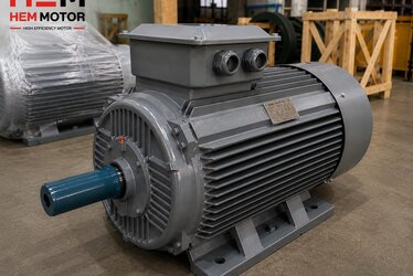
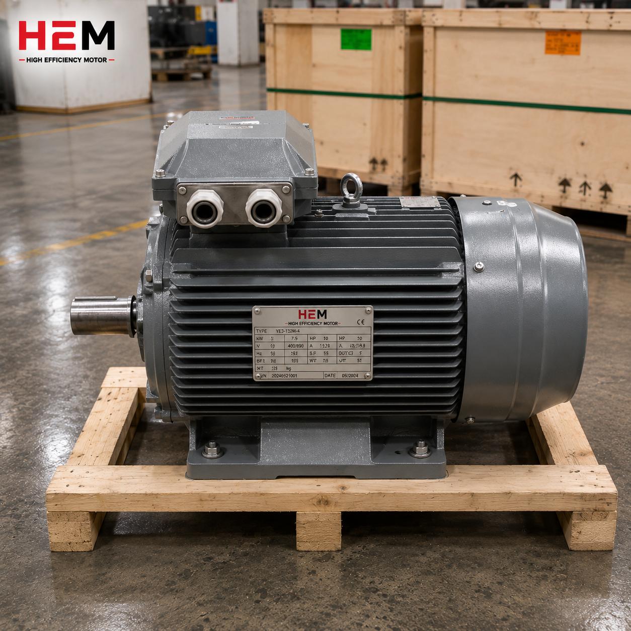
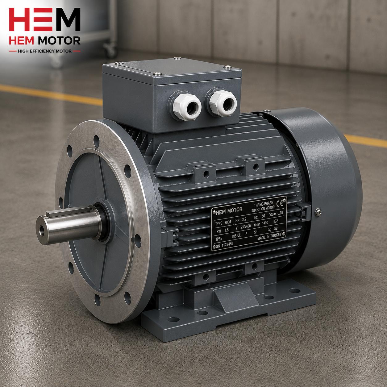
HEM Motor manufactures and supplies electric motors from stock in IE3 and IE4 efficiency classes, from 0.25 kW up to 355 kW, in IEC 56-355 frame sizes. Our motors are available at 1000, 1500 and 3000 rpm, as well as in 6- and 8-pole low-speed options. Cast iron and aluminum body alternatives, 100% copper windings, F class insulation, IP55 protection and S1 continuous duty are among our standard features. Thanks to proper lamination pressing, quality low-loss silicon steel and careful impregnation processes, we aim to keep core hum and magnetic noise to a minimum. With the advantage of broad stock and fast supply, we can determine together the right pole and body combination for your projects where quietness matters. For all models and current electric motor prices please contact us, and you can review our entire asynchronous motor range in our Asynchronous / AC Motors category.
Frequently Asked Questions
Is my motor's 100 Hz hum a sign of a fault?
No. The 100 Hz hum coming from the stator core of an asynchronous motor running on a 50 Hz supply is a normal and unavoidable physical phenomenon caused by magnetostriction. This sound starts the moment power is applied, is independent of load and stops immediately when the supply is cut. Sounds that indicate a fault are usually higher-frequency clicks/rustles that continue even while the motor freewheels; those point to a bearing.
I want a quieter motor at the same power -- what should I look at?
First compare the sound power Lw (dB) and Lp dB(A) values declared per IEC 60034-9; at the same speed, a lower value means quieter. Then, if possible, choose a higher-pole (6/8-pole) low-speed model, a cast iron body and an IE3/IE4 efficiency class. Together these noticeably reduce both the hum and fan noise.
How do I reduce the fine whine that appears when running on a VFD?
That whine comes from the drive's carrier (switching) frequency. Raising the carrier frequency in the drive parameters (for example 8-16 kHz) shifts the tone above the hearing limit and reduces perceived noise; however, since it can increase drive heating, stay within the manufacturer's limits. Using a sine/dU/dt filter also protects the motor and softens the tonal noise. For VFD applications, prefer an F-insulated, well-impregnated motor.