English
 Türkçe
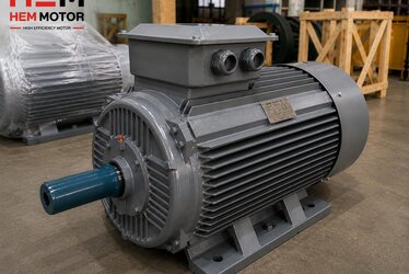
When buying an asynchronous motor, most purchasers look at power (kW), speed and mounting type. Yet one of the design decisions that quietly determines a motor's efficiency, heating behaviour and compatibility with the supply voltage is usually hidden behind the nameplate: the number of parallel paths (parallel circuits) in the stator winding. Two motors of identical rated power can look exactly alike from the outside, yet if the stator is wound with a different number of parallel circuits, the wire gauge, the per-phase current distribution, the current balance and therefore the efficiency class (IE3/IE4) will all differ.
In this article we explain the concept of parallel circuits from a HEM Motor engineering perspective, in a way that is simple but technically correct for buyers, machine builders and commissioning teams. The goal is to show why winding design is a "factory job" and what the real difference is between a rewound (repaired) motor and a brand-new, factory-wound, balanced motor.
What Is a Parallel Path (Circuit) in a Stator Winding?
In a three-phase asynchronous motor, each phase winding is formed by the coil groups placed in the stator slots, connected in series and/or parallel. Instead of forcing the entire phase current through a single path, the coil groups of one phase can be split into two, three or four equal "paths" and connected in parallel. The number of these equivalent current paths per phase is called the number of parallel paths, or in technical terms the number of parallel circuits (a).
The logic is simple: the total current per phase is fixed, but however many parallel paths you split it into, the current through each individual wire drops proportionally. This directly affects the conductor (enamelled copper wire) diameter used in the winding:
- Single parallel path (a=1): The full phase current flows through a single wire group, so either a very thick single wire or a multi-strand bundle is needed. Preferred at small powers and higher voltages.
- Two parallel paths (a=2): The phase current splits in two, half flowing through each path; thinner wire that fits the slot more easily can be used. Very common at medium powers.
- Four parallel paths (a=4): In high-power, multi-pole motors the current is distributed over four paths, giving advantages in slot fill factor and cooling.
The number of parallel paths cannot be chosen arbitrarily; it must be compatible with the pole count, the slot count and the coil-group layout. As a general rule the number of parallel circuits must divide the pole number (for example, a 4-pole motor may allow 1, 2 or 4 parallel paths, provided the winding scheme is built accordingly).
How Are Parallel Paths Related to Voltage?
In Turkey the line-to-line supply voltage is around 380/400 V (up to 415 V in some regions). The voltage a motor of a given power is wound for is set together with the number of turns and the number of parallel paths, because the voltage each coil sees is directly proportional to the number of turns and the connection type (star/delta).
Two concepts are frequently confused here and must be separated:
Star-Delta Connection ≠ Number of Parallel Paths
The star (Y) or delta (Δ) connection in the terminal box determines how the phase windings are connected to one another and changes the voltage the winding sees by a factor of √3. For example, a motor rated 400/690 V runs in delta on a 400 V supply and in star on a 690 V supply. By contrast, the number of parallel paths is how many ways the coils inside a single phase are split, and it cannot be changed externally from the terminals; it is fixed in the factory when the winding is laid. For starting-method selection, our guide on star-delta and starting methods covers the topic in detail.
Winding a motor for dual-voltage ratings such as 230/400 V (small powers) or 400/690 V (medium-large powers) determines both the connection type and at which voltage star-delta starting is possible. If the right combination of parallel paths and turns is not chosen, the motor either magnetically saturates at the required voltage (heating up, drawing high current) or loses torque because of low flux.
Current Balance: Why Must Parallel Paths Be Equal?
When you split a phase into two or four parallel paths, those paths must be electrically identical: the same number of turns, the same slot positions, the same resistance and the same inductance. Otherwise the current balance between the parallel paths is lost and circulating currents appear within them.
- Balanced parallel paths: Equal current flows through each path, heating is distributed evenly, phase currents stay balanced and efficiency remains high.
- Unbalanced parallel paths: If one path has lower resistance than another, more current flows through it, causing local overheating and extra loss; a difference (current imbalance) is measured between the phase currents.
- A broken parallel path: If one of the parallel paths breaks or short-circuits, the remaining paths must carry the load, leading to overcurrent, an unbalanced magnetic field, vibration and rapid winding burnout.
This is exactly why windings with parallel paths require a symmetrical winding pattern and careful slot distribution. A factory-laid stator winding achieves this symmetry with automatic machines and standardised templates; every motor is then measured on the test bench for no-load current and phase balance.
Copper Winding, Parallel Paths and Efficiency
One of the biggest contributors to a motor's efficiency class (IE3, IE4) is the winding loss (copper loss, I²R). Correctly splitting the phase current into balanced parallel paths reduces the current in each wire, lowering heat loss and allowing the wire to fit the slot better (a high fill factor). The 100% copper winding used in HEM motors has a lower resistivity than aluminium, so for the same cross-section it produces less loss and lower heating.
We cover the effect of winding material on efficiency and service life in our article on the difference between copper and aluminium winding. However good the parallel-path design is, a motor will not be long-lived if the winding insulation is inadequate; the insulation class is therefore at least as important as the winding design, as explained in our content on winding and insulation class (F/H).
How Does a Balanced Parallel Circuit Show Up in Efficiency?
Place two motors of the same power and frame side by side — one factory-wound and balanced, the other rewound/unbalanced — and the difference appears in these points:
- Equality of the per-phase current drawn at no load and under load — a balanced winding means balanced current.
- Lower winding temperature at full load — F-class insulation and even heat distribution extend service life.
- Low vibration and noise — an unbalanced magnetic field generates vibration; a balanced winding runs quietly.
- Nameplate efficiency held in the field — a poorly wound motor cannot actually achieve its nameplate efficiency.
The Difference Between Rewinding and Factory Winding
Rewinding a burnt-out motor is the situation in which it is hardest to exactly recover the original symmetry of a parallel-path winding. In hand winding, the slot distribution, the number of turns and the parallel path symmetry vary from workshop to workshop; the wire gauge is often chosen approximately and the fill factor drops. The result: higher copper loss, lower efficiency and usually a motor that drops to a lower efficiency class.
For this reason, especially in small and medium frames, it is often more sensible to buy a new, factory-wound, tested motor instead of rewinding. As HEM Motor, the stator winding of our asynchronous motors is produced on automatic machines with a balanced number of parallel circuits and standard winding schemes; every motor is tested for phase balance, insulation resistance and no-load current before dispatch. Combined with a cast-iron body, IP55 protection and F-class insulation, this means a long-lived, balanced operation in the field. For current models and electric motor prices you can request a quote.
What to Check About Parallel Paths When Buying
An ordinary buyer does not need to draw the winding scheme; it is enough to ask the following to get the right motor:
- What voltage is the motor wound for? (230/400 V or 400/690 V) — it must suit your supply and starting method.
- Was it factory-wound, or is it a rewound (repaired) motor? — critical for efficiency and life.
- Is the winding 100% copper? — aluminium lowers cost but affects efficiency and life.
- Is the insulation class F (or H) and the protection IP55? — essential for hot and dusty environments.
- Is a test report (no-load current, insulation resistance) provided? — this is proof of a balanced current balance.
For a balanced, factory-wound motor with the right mounting type and efficiency class, you can review our IE3 efficient asynchronous motor product range and request a quote at the power and speed suited to your application.
Frequently Asked Questions
Does the number of parallel paths change the motor's power?
No, it does not change the power directly; power is mainly set by the frame, pole count and magnetic design. However, the number of parallel circuits determines how many wires the per-phase current is split between, and therefore the wire gauge, the copper loss and the heating. This in turn affects with what efficiency and at what temperature the same power is produced. In short, parallel paths do not set the power but how efficiently and how evenly that power is delivered.
If one parallel path breaks, will the motor keep running?
It usually keeps running for a short while, but this is dangerous. Because of the broken path, the remaining parallel paths carry excess current, the affected phase overheats, the current balance is lost and the magnetic field becomes asymmetric. The result is vibration, noise and rapid winding burnout. If you notice a clear imbalance in the phase currents, the motor should be stopped and inspected; in most cases replacing it with a new, factory-wound motor is the safest solution.
Does a rewound motor keep the original parallel-path structure?
An attempt is made, but in practice it is hard to reproduce exactly. The slot distribution, number of turns and parallel path symmetry of the original winding cannot be fully imitated under workshop conditions; the wire gauge is chosen approximately and the fill factor drops. This usually means higher loss and a lower efficiency class. Especially in small-to-medium frames, buying a new, factory-wound and tested asynchronous motor is the safer choice for both efficiency and long life.