English
 Türkçe
When the rotor of an asynchronous motor cannot turn because of an unexpected mechanical obstruction, or cannot overcome the load on starting, locked-rotor current flows through the windings. This current is many times the motor's rated current and drives the winding to dangerous temperatures very quickly. A jammed conveyor, a blocked pump, a stuck crusher or incorrect starting can all stall the rotor and put the motor into this dangerous condition. In this guide we address locked-rotor (stall) protection and withstand time on asynchronous motors in terms of tE time, stall detection and correct selection, explaining how to protect your motor and what to watch for when buying.
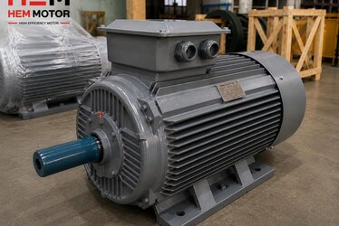
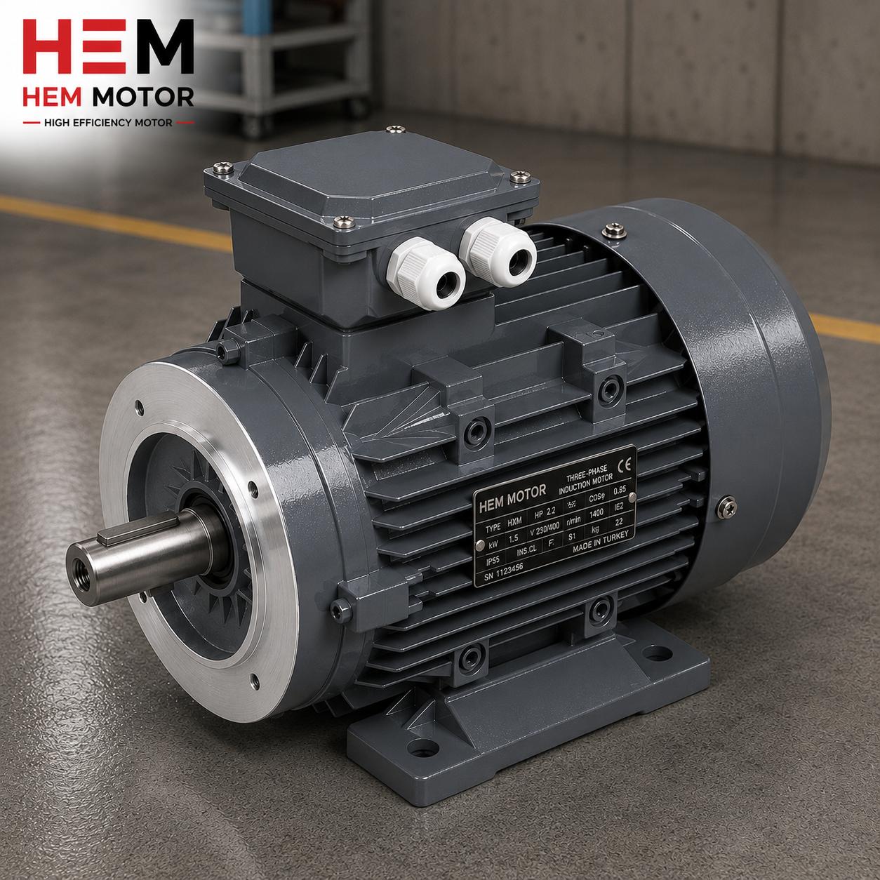
At HEM Motor we supply motors in IE3 and IE4 efficiency classes, with class-F insulation and robust windings, together with the right protection devices. First, let us clarify what the locked-rotor phenomenon is and why it is so critical.
What Is Locked Rotor (Stall) and Why Is It Dangerous?
In an asynchronous motor the rotating magnetic field induces current in the rotor and produces torque. When the rotor turns, the rotor (slip) frequency falls and the winding current drops to a normal level. But if the rotor cannot turn, the slip becomes 1 (fully locked); in this case the motor behaves almost like a short-circuited transformer and locked-rotor current flows through the windings. This current is several times the motor's normal operating current.
The danger lies in the heat produced by this high current. Because the rotor does not turn, the fan cannot cool; moreover, all the energy is converted to heat. The winding temperature can exceed the insulation limit within seconds. If protection does not act quickly enough, the insulation is permanently damaged and the motor burns out. This is exactly why locked-rotor protection is an inseparable part of motor selection and supply.
tE Time: The Key to Withstand Time
The tE time is the maximum time a motor can withstand a locked-rotor condition (or overload) without insulation damage. In other words, it is the time from the moment the motor stalls until the winding temperature reaches the permitted limit. This time depends on the motor's starting temperature, the locked-rotor current and the insulation class. The shorter the tE time, the faster the protection device must trip.
- Short tE time: The motor is less tolerant of stalling; a very fast overcurrent/thermal protection is essential.
- Hot start: If the motor stalls while already warm, the tE time is noticeably shorter than from a cold start.
- High locked-rotor current: The higher the current, the faster the heating and the narrower the protection margin.
The tripping characteristic of the protection device must be chosen to trip faster than the motor's tE time. Correct setting of the thermal relay, motor protection circuit breaker or motor protection relay is therefore vital. We cover the protection devices to request with the motor in detail in our guide on buying electric motor protection devices.
Stall Detection Methods
There are several ways to detect a locked rotor or stall; the right solution depends on how critical the application is:
- Thermal overcurrent relay: The most common method. It monitors current continuously and trips before the tE time when locked-rotor current flows. It must be set to the correct current value.
- Motor protection circuit breaker: Provides both overload and short-circuit protection; the magnetic trip responds quickly to locked-rotor current.
- PTC thermistor / embedded temperature sensor: A sensor embedded in the winding measures temperature directly. Because it monitors actual temperature rather than current, it is the most reliable protection method; recommended for heavy-starting and frequently stalling applications.
- Electronic motor protection relay: Offers comprehensive protection by evaluating current, phase imbalance, locked-rotor time and a thermal model together.
Especially in heavy applications such as crushing-screening and mining, where the rotor can physically jam, using an embedded temperature sensor together with current protection is the safest approach.
The Relationship Between Starting Method and Locked Rotor
The instant of starting is when the motor is closest to its locked-rotor current. With direct-on-line (DOL) starting the motor briefly draws close to full locked-rotor current; star-delta or soft starter reduces this current. In heavy-starting applications, the wrong starting method causes the motor to enter a locked-rotor-like stress on every start. On the choice of starting method our guide on star-delta vs soft starter on asynchronous motors, and for drive-based solutions our article on asynchronous motor with a frequency drive (VFD), provide guidance. A frequency drive adds a layer of protection with controlled starting and current limiting during a stall.
Resistance to Stalling Through Correct Motor Selection
- In applications with high stall risk, motors with high starting torque and a robust rotor should be preferred.
- Class-F insulation provides a wider temperature margin, giving the tE time some breathing room.
- An embedded PTC thermistor option should be requested from the outset on critical drives.
- The protection device must be coordinated with the motor's locked-rotor characteristic and tE time.
For the general structure and selection parameters of asynchronous motors you can browse our IE3 asynchronous electric motors product group, and contact us for a correctly protected motor and current electric motor prices.
The Relationship Between Locked-Rotor Current and Heating
The basic problem the motor experiences in a locked-rotor condition is that the high current drawn is converted to heat in a very short time. In normal operation the rotor turns, so slip is low and the current through the winding is under control; in addition, the fan on the shaft cools the motor. When the rotor locks, both of these protection mechanisms disappear: the current surges, and the fan, being motionless, cannot cool. The result is an uncontrolled rise in winding temperature. This is why a locked rotor is one of the fastest damage scenarios a motor can face.
The speed of heating depends on the magnitude of the locked-rotor current and the motor's starting temperature. A cold motor can withstand it longer than a hot motor, because the winding has more "thermal buffer" margin before reaching the insulation limit. In a motor that stalls while already warm, this margin narrows greatly and damage comes much faster. For this reason the stall risk is more critical in motors that start and stop frequently and heat up on every start.
The Difference Between Overload and Locked Rotor
Overload and locked rotor may look similar but are different. In overload the motor turns but carries a load above its capacity; the current is slightly above rated and heating is relatively slow. In a locked rotor the motor cannot turn at all; the current is much higher and heating is much faster. The protection strategy must answer both conditions: the thermal relay catches slow overload, while the magnetic/fast protection catches sudden locked-rotor current. A good motor protection device distinguishes these two scenarios and trips at the right speed.
Insulation Class and Temperature Rise
The motor's insulation class determines the maximum temperature the winding can withstand. Class-F insulation is a widely used class offering a broad temperature margin. In sudden-heating scenarios such as a locked rotor, higher insulation resistance gives the motor an additional safety margin. However, the insulation class alone is not enough; without correct coordination of the protection device, even the best insulation cannot withstand prolonged locked-rotor current. For this reason motor selection and protection selection cannot be thought of separately.
We explained how to check insulation resistance on a stock motor and how the megger test is performed in our article on insulation resistance and the megger test on asynchronous motors. These checks before commissioning ensure the motor starts in the field with healthy insulation.
Stall Risk by Application
Not every application has the same stall risk. In some drives the likelihood of the rotor physically jamming is very high:
- Crushing-screening and mining: Large pieces can clog the crusher; the rotor can stop suddenly. High stall risk.
- Conveyor drives: A belt jam or foreign object can put the motor into a locked rotor.
- Mixers and augers: Dense material or buildup can block the shaft.
- Pumps: A foreign object or dry running can stop the rotor.
We addressed emergency replacement and the post-stall swap process for conveyor motors in our article on conveyor belt motor emergency replacement and swap. In high-stall-risk applications, planning the protection hardware correctly from the outset protects both the motor and production continuity.
Safe Supply with HEM Motor
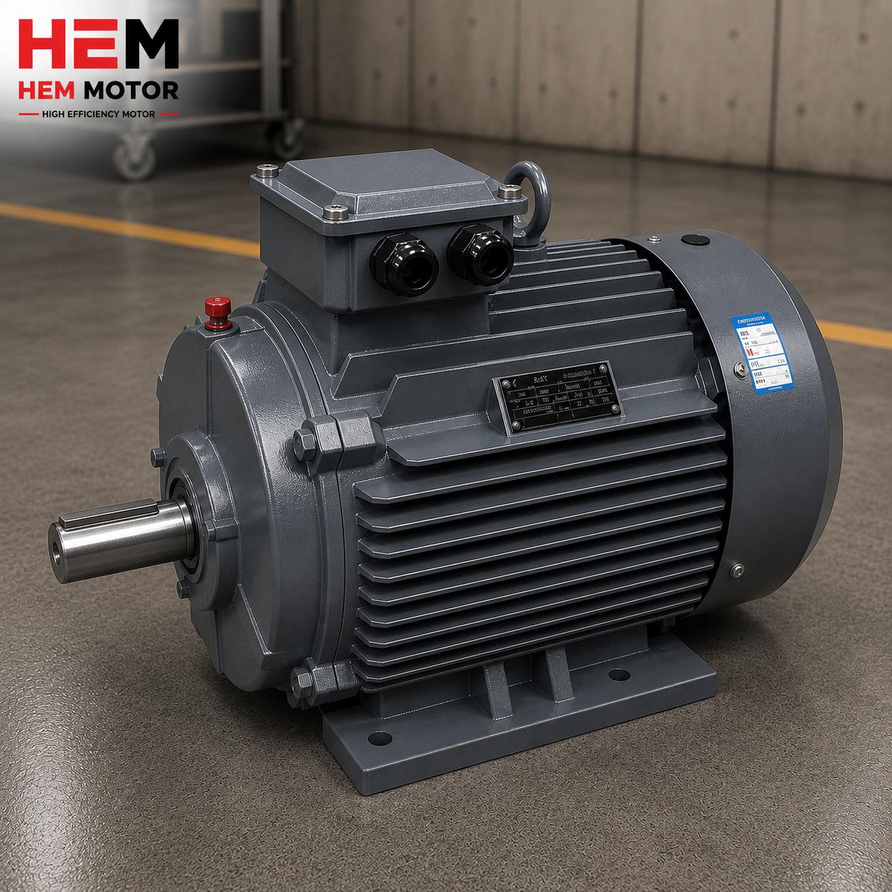
Locked-rotor protection is not just the choice of a device; it is the planning of the motor, insulation, starting method and protection hardware as a coherent whole. At HEM Motor we assess your application's stall risk and recommend your motor with the correct insulation class, an embedded temperature sensor where needed and suitable protection hardware. Our standards of robust rotor construction and class-F insulation provide a safe margin against stalling under heavy-duty conditions.
Frequently Asked Questions
How long does it take for locked-rotor current to burn out a motor?
This time depends on the motor's tE time and is generally very short; it becomes even shorter if the motor is already warm. Because the rotor does not turn, the fan cannot cool and all the energy is converted to heat, so the winding temperature can reach the insulation limit quickly. The exact time varies with the motor's design and insulation class; rather than giving an absolute value, we emphasize that the protection device must be coordinated to trip faster than the motor's tE time.
Is a thermal relay alone sufficient against a locked rotor?
A correctly set thermal overcurrent relay provides adequate protection in many applications; however, it may not be sufficient alone in heavy and frequently stalling applications where the rotor can physically jam. In these cases a PTC thermistor embedded in the winding or an electronic motor protection relay offers more reliable protection by monitoring the actual winding temperature. The safest approach is to use current protection together with embedded temperature protection. If you send us your requirement, we will recommend the appropriate protection combination.
In an application with high stall risk, should I buy the motor at one rating higher?
The way to reduce stall risk is not to oversize the motor but to choose the right starting method, the right protection hardware and a motor with suitable starting torque. An oversized motor causes a loss of efficiency and power factor at low load and does not provide a lasting solution against stalling. The correct solution is to supply a motor with high starting torque and a robust rotor, together with an embedded temperature sensor and a protection device coordinated to the tE time. If you use a frequency drive, its current-limiting feature provides an additional layer of protection.