English
 Türkçe
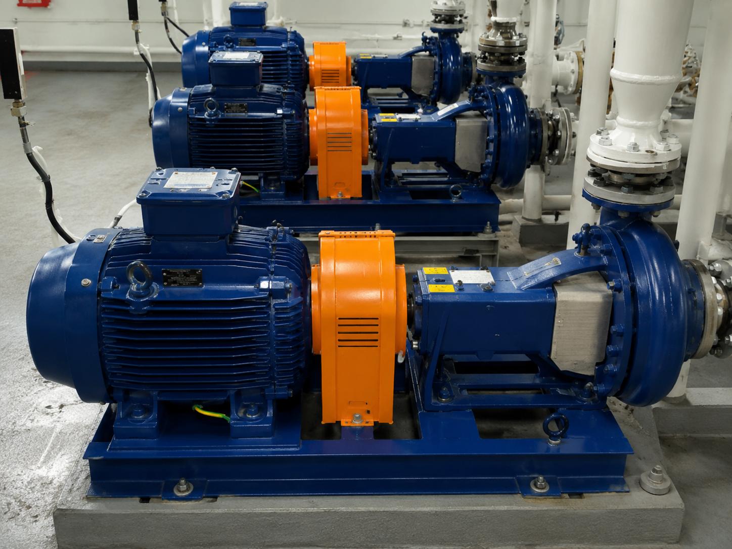
Peristaltic pumps move fluid through a transfer principle in which only a flexible hose touches the medium, free of friction losses and contamination; however, this rugged design creates a very specific load profile on the motor side. Correct peristaltic hose pump motor selection requires high starting torque, very low output speed and constant-torque demand to be addressed together. In this guide we explain step by step how to power these pumps correctly using HEM Motor IE3/IE4 electric motors together with worm-gear or bevel-helical reducers, and how to achieve accurate dosing and flow control.
How a Peristaltic (Hose) Pump Works
A peristaltic pump operates as rollers (or sliding shoes) on a rotating rotor compress a flexible hose and push the fluid forward. The closed volume formed at the occlusion point travels toward the pump outlet as the rotor turns, so the fluid contacts only the inner surface of the hose. This makes it possible to transfer abrasive slurries, chemicals, food fluids and solids-laden suspensions without contamination or sealing problems.
Compressing the hose, which is the heart of the pump, creates a pronounced and periodic torque pulsation (occlusion torque) on the motor shaft. Each roller squeezing the hose produces a sudden resistance, which means motor selection must account for the peak torque in addition to the average torque.
Why High Torque and Low Speed Are Needed
Peristaltic pumps typically run between 10 and 60 revolutions per minute, and in some dosing applications at far lower output speeds. A standard asynchronous motor running at 1500 rpm cannot be coupled directly to this speed; a speed-reducing gearbox must always sit in between. This is precisely where the high-torque low-speed combination calls for an IE3/IE4 motor paired with a worm-gear or bevel-helical reducer.
Peak Starting Torque
In a stopped peristaltic pump the hose is held compressed by the rollers. At the first moment of movement the motor must overcome this occlusion and set the fluid in the full hose into motion, so the starting torque can be noticeably above the normal running torque. The torque class of the asynchronous motor is critical here. For details on starting behavior, see our Asynchronous Motor Torque Classes article.
Continuous (S1) Torque
Peristaltic pumps are mostly installed for long, uninterrupted transfer or dosing. The motor is therefore expected to deliver its rated torque continuously in the S1 duty regime without exceeding its thermal limits. Class F insulation and IP55 protection provide a safe temperature margin and dust/water protection under this continuous load.
Constant-Torque Load Profile and Motor Sizing
A peristaltic pump exhibits classic constant-torque load behavior: the required torque is largely independent of speed and is set by hose diameter, pressure and fluid density. This is fundamentally different from the cubic power rise with speed seen in centrifugal pumps. We detail how the constant-versus-variable distinction affects selection in our Variable Speed Motor Selection article.
To determine motor power correctly, the path is to work backward from the required output torque. First the torque (Nm) the pump demands at the desired output speed is established; this torque is referred back to the motor shaft accounting for gear ratio and efficiency; then speed and torque together yield the power in kW. For the general power-torque relationship and a step-by-step calculation, our Motor Power Calculation guide is the reference.
Reducer Choice: Worm-Gear or Bevel-Helical?
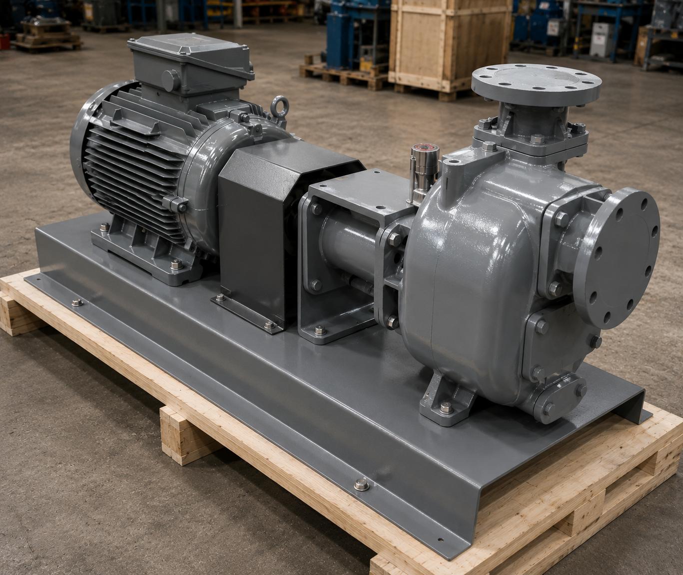
The very low output speed and high torque demand favor a worm-gear reducer in most peristaltic applications. The worm-gear reducers in the HEM30–HEM130 housing range offer a wide reduction ratio between 1/7.5 and 1/100, delivering high reduction in a single stage and forming a compact, quiet drive. For lines requiring higher efficiency and continuous heavy duty, bevel-helical (K-series) reducers are preferred; this series offers superior efficiency and high torque capacity in right-angle drives.
Reducer efficiency directly affects motor power: in worm-gear units efficiency varies with ratio and can be high at low ratios but lower at very high ratios, whereas bevel-helical reducers generally show higher efficiency. Therefore reducer efficiency must always be considered in the denominator when selecting motor kW. To decide between a complete unit and a separate motor + reducer, our Geared Motor vs Separate comparison is a useful guide.
Dosing and Flow Control with a VFD
One of the strongest features of peristaltic pumps is that output flow is directly proportional to speed: because hose volume is fixed, doubling the speed roughly doubles the flow. This linear relationship makes it very easy to perform precise dosing by changing motor speed with a frequency inverter (VFD). Because of the constant-torque characteristic, the motor must be able to deliver rated torque even at low speeds, which means inverter-motor compatibility and, if required, forced cooling (external fan) should be evaluated.
- Linear flow control: The speed-flow relationship gives repeatable results in recipe-based dosing.
- Wide turndown range: A single pump covers a very broad flow window with a VFD.
- Soft start: The inverter softens the starting impulse from occlusion torque with controlled acceleration.
- Low-speed torque protection: Motor thermal capacity must be preserved at low speed under constant-torque load.
- Energy efficiency: IE3/IE4 motors run with low losses even at partial load.
Abrasive/Chemical Slurry and Torque Pulsation
Most applications where peristaltic pumps are chosen involve abrasive or chemical fluids: mining slurry, sludge, lime milk, paint, food dough and similar. These fluids increase torque demand due to high viscosity and solids content; in addition, the periodic torque pulsation at the hose occlusion point requires the motor and reducer to be selected for peak loads. For this reason, service factor and safety margin should be generous even in this seemingly constant load.
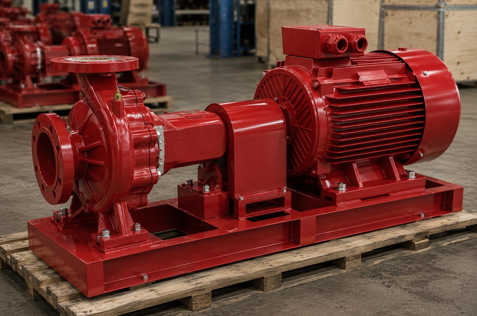
The motor housing material also matters: in harsh industrial environments, cast iron IE3/IE4 motors provide an advantage in mechanical durability and heat dissipation. The 100% copper winding offers low losses and long life in continuous S1 duty. B5 or B35 flange mounting types are preferred for direct connection to the reducer.
Peristaltic Pump Motor Selection Checklist
- Output torque (Nm): The real running torque set by hose diameter, pressure and fluid density.
- Output speed (rpm): The pump rotor speed corresponding to the desired flow.
- Reducer ratio and type: Worm-gear (HEM30–HEM130, 1/7.5–1/100) or bevel-helical K-series.
- Reducer efficiency: Must be included in the denominator when selecting motor kW.
- Starting torque margin: Peak torque to overcome the compressed hose must be met.
- Service factor: Safety margin for torque pulsation and abrasive load.
- Duty cycle: S1 for continuous transfer; IP55 protection, Class F insulation.
- Speed control: VFD compatibility for dosing and cooling at low speed.
- Mounting type: B5/B35 flange for connection to the reducer.
To select the right pump motor family, you can review our product groups and supply from stock from our Reducer Electric Motors and Pump Electric Motors categories for reducer-driven applications. For the general range and pricing, see our electric motor prices page. To understand the difference in centrifugal pump applications, our Centrifugal Pump Motor Selection article is also helpful.
Hose Life, Speed Limit and the Motor Relationship
In peristaltic pumps the most critical consumable is the hose; because it is compressed and released many times per revolution, it is subject to fatigue. The higher the motor speed, the more compression cycles the hose undergoes per unit time and the shorter its life. For this reason manufacturers usually recommend a certain maximum output speed, and the motor and reducer must be selected so as not to exceed this upper limit. Running at low to medium speed both extends hose life and reduces the vibration caused by occlusion-related torque pulsation.
This balance requires the gear ratio and motor base speed to be chosen together. For example, if a lower hose compression frequency is desired, using a 6-pole (1000 rpm) motor with a smaller gear ratio can provide the same flow with fewer cycles. This approach reduces hose replacement frequency and lowers operating cost. To determine the correct power-speed combination, the flow-head based method described in our Deep Well Pump Motor Selection article can also be useful.
Backflow and Braking Behavior
One advantage of a peristaltic pump is that when it stops, the hose remains compressed, forming a natural backflow barrier (self-sealing). However, in applications with high discharge head, the pressure accumulated in the system at standstill can apply a reverse torque to the motor shaft. The self-locking tendency that worm-gear reducers exhibit at high ratios can be helpful here; nevertheless, the reducer type and ratio should be selected carefully for safe stopping.
Supply and Stock from HEM Motor
HEM Motor manufactures and supplies from stock its 0.55–355 kW IE3/IE4 three-phase asynchronous motors, HEM30–HEM130 worm-gear reducers and K-series bevel-helical reducers. Procuring the motor and reducer as a matched drive package for peristaltic pump duty shortens both assembly and commissioning time. Class F insulation, IP55 protection and 100% copper winding come as standard; B3/B5/B14/B35 mounting options ensure compatibility with any reducer interface.
Making a selection that jointly evaluates the correct motor power, pole count and gear ratio according to the requirements of the dosing, transfer or chemical feed application on your production line is decisive for both energy efficiency and long equipment life. Keeping the safety margin generous for abrasive and viscous fluids ensures the motor runs without strain under unexpected torque peaks. Cast iron IE3/IE4 motors provide mechanical durability and superior heat dissipation under continuous heavy duty, forming an ideal foundation for peristaltic pump drives.
Frequently Asked Questions
Why is a separate reducer needed for a peristaltic pump?
Peristaltic pumps run at very low output speeds such as 10–60 rpm, whereas standard asynchronous motors turn around 1500 or 3000 rpm. To reduce this speed and increase torque, a worm-gear (1/7.5–1/100) or bevel-helical reducer must sit in between; the reducer both brings the speed down to a suitable value and provides the required high torque by multiplying it with the ratio.
Is a frequency inverter mandatory for dosing?
In dosing applications requiring precise and variable flow, using a VFD is very advantageous because flow is linearly proportional to speed in a peristaltic pump. If a single fixed flow is sufficient, a VFD is not mandatory; however, an inverter is recommended because it provides soft start and a wide turndown range. Motor cooling should be reviewed in constant-torque operation at low speed.
How do I calculate motor power from output torque?
First determine the output torque (Nm) and output speed the pump requires, refer this value back to the motor shaft using the gear ratio and efficiency, then find the kW power from speed and torque. Add a safety margin for service factor and peak starting torque. You can find the step-by-step method in our Motor Power Calculation guide and select the appropriate power from HEM Motor stock.