English
 Türkçe
Variable-frequency-controlled hydrophore, that is, booster pump systems, are the most efficient way to maintain constant water pressure in modern buildings and industrial plants. Unlike classic on-off hydrophores, a VFD-controlled hydrophore continuously adjusts the pump motor speed according to water demand; as a result, the network pressure barely fluctuates even when the number of open taps changes. In this article we cover the correct hydrophore pump motor selection for a booster pump driven by a frequency drive (VFD): the constant-pressure logic, PID control, variable-flow behavior, and correct power supply, all from a purchasing perspective. Our goal is to help you confidently order a drive-compatible, long-life motor that can be supplied quickly from stock while you plan your project. From residential complexes to hotels, from hospitals to factories, stable water pressure means both comfort and process safety in every facility, and correct motor selection is the foundation of that stability.
Constant-Pressure Logic: Why Should a Booster Pump Be VFD-Controlled?
In conventional hydrophores, the pump starts when tank pressure drops to a low limit and stops when it reaches the high limit. This on-off cycle both creates pressure swings and forces the motor into frequent starts and stops. Frequent starting makes the motor produce its starting current again and again and overheats the windings. In the VFD-controlled hydrophore concept, the system holds a target pressure (setpoint); as pressure drops, the drive raises the motor speed, and as demand decreases it lowers the speed. As a result, the pump can run without ever stopping, at a flow proportional to demand.
This mode of operation means the motor runs over a wide speed range instead of a fixed 50 Hz. Therefore the motor you select must heat safely, cool adequately, and have drive-compatible winding insulation not only at the rated point but also at low speeds. For this reason, in our pump electric motor range, IE3 and IE4 efficiency-class models with 100% copper windings suited to continuous (S1 duty) operation are preferred. Copper winding provides both low losses and high thermal endurance, allowing the motor to safely complete its life under variable-speed operation.
A constant-pressure system also reduces hydrophore surges and water hammer, especially in multi-story buildings. Because the pump accelerates with a smooth ramp, sudden pressure shocks in the pipeline are largely eliminated. This extends the life of both the plumbing and the motor. The motors we supply with manufacturer assurance are selected to work seamlessly with such constant-pressure panels.
Critical Motor Parameters for Constant Pressure
- Speed (number of poles): Most booster pumps run at 2900 rpm (2-pole); a 2-pole motor is standard for multistage centrifugal pumps requiring high pressure. Where lower pressure and higher flow are needed, a 4-pole (1450 rpm) motor can be chosen.
- Power (kW): Should be selected according to the shaft power at the pump highest flow-pressure point, with a safety margin. An undersized motor overheats at peak demand; an oversized one loses efficiency at partial load.
- Mounting type: B5 flange for vertical inline pumps; B3 foot or B35 combined frames for horizontal coupled pumps.
- Protection class: IP55 is standard against water and humidity; a higher class may be requested if there is splashing in the pump room.
- Insulation class: Class F insulation offers sufficient thermal margin against the extra heat load brought by drive operation.
PID Control: The Brain That Keeps Pressure Constant
The PID control loop inside the frequency drive reads the actual pressure of the system from a pressure transmitter and compares it with the setpoint. As the difference (error) grows, the drive increases the motor frequency; once pressure reaches the setpoint, it stabilizes the speed. Correct tuning of the proportional (P), integral (I), and derivative (D) terms is critical so that pressure neither oscillates excessively nor responds too slowly. A poorly tuned PID loop makes the motor constantly speed up and slow down and wastes energy.
For PID control to work properly, the motor must respond cleanly to the drive. A motor that can produce torque at low speeds without exceeding its heating limit responds quickly and stably to pressure swings. To better understand motor selection and bearing arrangement under drive operation, you can review our guide on using a frequency drive (VFD) with an asynchronous motor.
Pressure Transmitter and Feedback
For the system to work correctly, the pressure transmitter should be located close to the pump outlet at a turbulence-free point. A poorly located sensor misleads the PID loop, causing the motor to needlessly speed up and slow down and therefore overheat. Correct feedback is decisive for both energy savings and motor life. The measuring range of the transmitter should suit the system pressure, and its wiring should connect to the analog input of the drive with shielded cable.
Sleep Mode and Single-Pump Saving
Modern constant-pressure drives have a sleep mode that stops the motor when demand ceases entirely. When demand resumes, the drive gently wakes the motor. This way, no energy is consumed at night and the motor does not run needlessly. So that the sleep-wake cycle is not stressful for the motor, the starting ramps must be set correctly and the motor must withstand frequent starting.
Variable Flow: Pump Laws and Energy Savings
The greatest advantage of a booster pump lies in variable flow. According to the affinity laws, flow is directly proportional to speed, pressure varies with the square of speed, and power varies with the cube of speed. So when you halve the pump speed, the power consumption can theoretically fall to about one-eighth. During night or low-demand hours, variable flow delivers significant energy savings. This cubic relationship is the main reason VFD-controlled hydrophores pay back their investment cost in a short time.
For this saving to materialize, the motor must maintain its efficiency at low speeds. IE3 and IE4 class motors offer high efficiency even at partial load, so they are preferred in variable-flow booster applications. When choosing a hydrophore electric motor, you should look not only at the rated efficiency but also at the partial-load efficiency curve. An efficient motor carries the total energy performance of the system upward without wasting the saving the drive provides.
Cooling Problem at Low Speed
The fan of a standard TEFC (totally enclosed fan-cooled) motor rotates on the same axis as the shaft. When the speed drops, the fan slows too and cooling decreases. If a booster pump will run continuously at low speed but high torque, a motor with an external (forced) cooling fan should be considered. Our article on selecting an IE4 motor with external forced cooling fan offers detail. In most hydrophore applications, however, flow is proportional to speed, so the load also decreases at low speed and standard cooling is sufficient.
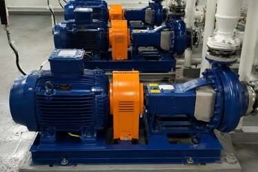
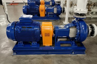
Multiple Pumps and Cascade Operation
In large facilities, multiple pumps are operated in cascade instead of a single pump. While one drive runs the lead pump at variable speed, backup pumps start at fixed speed as demand increases. In this architecture, at least one motor must be drive-compatible and the others suitable for direct-on-line starting. Having all motors in the same efficiency class and compatible power ensures balanced operation. With the stock-supply advantage, you can procure all the motors you need for multi-pump systems within the same batch.
Correct Power Supply and Stock Advantage
When designing a booster system, sizing the motor power to the pump operating point should be neither too much nor too little. An oversized motor increases both the initial investment and partial-load inefficiency; an undersized one falls short at peak demand and shortens its life through overheating. The correct power is found by adding a reasonable safety margin to the shaft power at the intersection of the pump curve and the system curve. The shaft-power curve provided by the pump manufacturer is the starting point of motor selection.
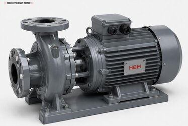
Fast supply from stock is critical to completing your projects on time. Our IE3 and IE4 pump electric motors, offered with manufacturer assurance, are kept in stock in frequently requested power and speed combinations; this shortens the process from quotation to delivery. To review the product family of these high-efficiency, drive-compatible motors, you can visit our electric motors for hydrophore category. For current electric motor prices and stock availability, you can contact us.
Pre-Order Checklist
- Has the pump shaft power and maximum operating point been determined?
- Do the speed (2 or 4 pole) and mounting type (B3/B5/B35) suit the pump?
- Is the motor drive-compatible, with winding insulation suitable for inverter operation?
- Is the protection class (IP55) adequate for the pump room conditions?
- Do the efficiency class (IE3/IE4) and lead time suit the project schedule?
- Do the shaft diameter and flange dimensions match the pump body exactly?
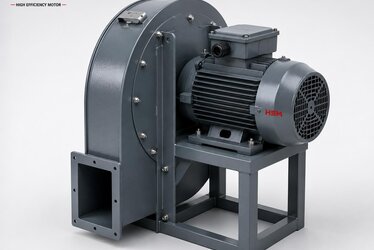
Separating Fire and Clean-Water Lines
The same facility may have both a clean-water booster line and a separate fire pump line. Fire pump motors are selected for sudden engagement and reliability rather than pressure stability; booster motors are optimized for energy efficiency and continuous operation. Because the motor needs of these two applications differ, the correct duty type and protection class must be evaluated separately for each line. Procuring motors suitable for both applications from a single supplier simplifies installation and service processes.
Frequently Asked Questions
Which speed motor is used in a VFD-controlled hydrophore?
Since most booster pumps produce high pressure, they run with 2-pole (2900 rpm) motors. Because the drive already varies the speed, the motor rated speed is chosen according to the design operating point of the pump. In some low-pressure, high-flow applications a 4-pole motor may also be preferred. The speed selection should be evaluated together with the pump curve and the desired pressure-flow point.
Is a drive-fed pump motor different from a standard motor?
Although the basic frame is the same, it is important that the winding insulation of a drive-fed motor withstands voltage spikes and that it cools adequately at low speed. Our IE3 and IE4 class, 100% copper-wound motors are suitable for this operation; a forced cooling fan is recommended if it will run for long periods at low speed and high torque. A correctly selected motor fully reflects the saving the drive provides.
Should I buy the motor alone or together with the pump?
Depending on your needs, we can supply only the motor or provide support on pump-motor compatibility. What matters is that the mounting type (such as a B5 flange) and shaft diameter match the pump body exactly; we recommend clarifying these dimensions before ordering. Thanks to fast delivery from stock, you can quickly obtain a suitable replacement for a faulty motor.