 English
 Türkçe
IE5 class synchronous reluctance (SynRM) motors are a new generation of high-efficiency motors that operate on the principle of reluctance torque with a magnet-free rotor structure. The fundamental difference from asynchronous motors is that they cannot run on their own when connected directly to the grid. A SynRM motor must always be commissioned together with a suitable variable frequency drive (VFD) as a package. At the heart of commissioning lies the drive's motor identification process, known as auto-tune (motor identification). In this article we cover the auto-tune concept, the difference between static and rotating tuning, the identified parameters, correct motor type selection in the drive, and field issues, together with a comprehensive commissioning checklist backed by manufacturer assurance.
Why Is an IE5 SynRM Motor Drive-Dependent?
Asynchronous motors produce torque by inducing current in the rotor from the rotating stator field, which is why they can start directly on the grid. In a synchronous reluctance motor, the rotor has no winding, cage, or magnet; it is designed around the saliency difference between axes where magnetic flux flows easily (low reluctance) and where it is opposed (high reluctance). The rotor follows the stator's rotating field at synchronous speed. The only element that ensures this synchronization is the drive that controls current at the correct phase and amplitude. When voltage is applied directly to a SynRM motor without a drive, the rotor cannot catch the rotating field, the motor stalls, and draws excessive current. This is why an IE5 motor drive package is an inseparable whole. Our article on why an IE5 synchronous reluctance motor will not run without a drive details this dependency.
What Is Auto-Tune (Motor Identification)?
Auto-tune is the process by which the drive measures the electrical and magnetic characteristics of the connected motor and models them for its own control algorithm. The drive applies controlled test signals to the motor and computes the motor's internal parameters from the current-voltage responses it reads back. In SynRM control, this step is critical because reluctance torque relies entirely on the difference between d-axis and q-axis inductance; the drive cannot produce correct torque without knowing these values.
Parameters Identified During Auto-Tune
- Stator resistance (Rs): Copper winding resistance; needed for low-speed torque and voltage drop compensation.
- d-axis inductance (Ld): Inductance along the axis where flux flows easily; determines the magnetizing current.
- q-axis inductance (Lq): Inductance along the axis where flux is opposed; determines the torque-producing component.
- Saliency ratio (Ld/Lq): The key indicator of SynRM efficiency and torque capability.
- Magnetization curve: Data describing how inductance changes with current, modeling the saturation effect.
When these parameters are extracted correctly, the drive can use the MTPA (maximum torque per ampere) strategy to produce the highest torque with the least current at every operating point; when extracted incorrectly, efficiency drops and vibration and overcurrent faults appear.

The Difference Between Static and Rotating Tune
Auto-tune is performed in two basic modes, and which one to choose depends on field conditions.
Static (Standstill) Identification
During static tune, the rotor does not turn. The drive measures Rs, Ld, and Lq with the rotor stationary by applying DC and high-frequency test signals. The greatest advantage of this method is that there is no need to decouple the motor from the mechanical load; it can be performed even with the load connected. It is preferred for motors whose coupling cannot be removed or that remain connected to a pump or gearbox. The disadvantage is that it does not provide saliency and inertia data as precisely as rotating tune.
Rotating Identification
During rotating tune, the drive turns the motor at low speed and measures the saliency position, magnetization curve, and system inertia under actual rotation. It gives the most accurate result and is especially valuable for initial rotor position detection in sensorless vector control. However, the motor must be decoupled (no load) or able to rotate freely. Rotating tune under load is risky for both the load and the motor and is generally not recommended.
Selecting the Correct Motor Type in the Drive
The most common and most critical mistake is selecting the wrong motor type in the drive. For a SynRM motor, the drive must be set to synchronous reluctance / SynRM / reluctance mode; if left in asynchronous (induction) mode, the drive expects slip current in the rotor, whereas a SynRM rotor has no slip. The result: the motor cannot start, oscillates, or trips on overcurrent. On some drives this selection is made under a "motor control mode" parameter and must be set BEFORE auto-tune.
Entering Nameplate Data Correctly
Before auto-tune, the motor nameplate values must be entered completely:
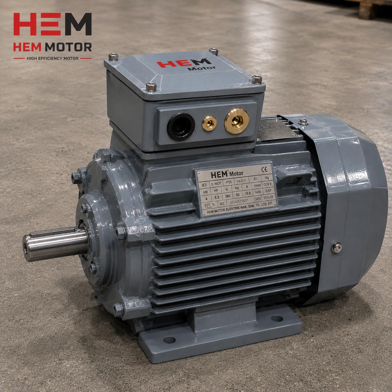
- Rated power (kW): The label power of the motor across the 0.55 kW to 355 kW range.
- Rated current (A): So the drive sets its current limits and overload protection to this value.
- Rated speed (rpm): Determines the pole count and synchronous speed.
- Frequency (Hz) and voltage (V): Define the base V/f and field-weakening point.
- cosφ and efficiency class: For SynRM the power factor differs from induction; it must be entered correctly.
Sensorless Vector Control vs Encoder Closed Loop
SynRM motors can be driven with two control architectures. Sensorless (encoderless) vector control estimates rotor position using the drive's mathematical model and high-frequency injection. It is low cost, simple to wire, and sufficient for most fan, pump, and compressor applications. Encoder closed loop reads the actual rotor position with an encoder; it is preferred in applications requiring full torque at zero speed, precise positioning, and high dynamics, such as cranes, elevators, and extruders. Which architecture to choose is determined by the application and the drive parameters are arranged accordingly. For details on drive parameterization, see our guide on drive parameterization and commissioning of an IE5 synchronous reluctance motor.
Commissioning Steps and First Start
- Set the motor type to SynRM / reluctance in the drive.
- Enter nameplate data completely (kW, A, rpm, Hz, V, cosφ).
- Choose static or rotating auto-tune according to the load condition and run it.
- When identification completes, verify that the resulting Rs, Ld, Lq, and saliency values are reasonable.
- Perform the first start at low speed; confirm the direction of rotation and correct it with the drive direction parameter if needed.
- Adjust the ramp (acceleration/deceleration) times to the load inertia.
- Verify MTPA and the current limit; observe vibration and temperature at full load.
Symptoms of Incorrect Tune and Their Solutions
- Vibration and noise: Usually caused by wrong Ld/Lq or incorrect motor type selection; repeat the tune.
- Cogging / sticking at start: The rotor initial position was detected incorrectly; rotating tune or encoder mode may be required.
- Overcurrent fault: The nameplate current was entered incorrectly or the ramp is too fast; review the values.
- Low torque / efficiency: Saliency was not measured correctly; redo the magnetization tune.
Installation compatibility should not be overlooked during the transition; we gathered the topic in our article on the drive and installation compatibility checklist when transitioning to an IE5 motor. For compatibility with different VFD brands, our content on compatibility of the IE5 motor with different drive brands provides guidance.
Post Auto-Tune Verification and Test Run
Reviewing the resulting values after motor identification completes is the most important habit that saves time in the field. The stator resistance calculated by the drive should be proportional to the motor power; a high Rs is expected at low powers and a low Rs at high powers. The Ld and Lq values must differ noticeably from each other; if the two values come out very close, the saliency was not measured correctly and the identification must be repeated. The test run follows these steps:
- No-load rotation test: The motor is rotated at low speed with no load; the current should be balanced and low, with no abnormal heating.
- Gradual loading: As the load is increased gradually, the motor current, drive DC bus voltage, and temperature are monitored.
- Speed sweep test: The speed is swept from low to rated and, if needed, into the field-weakening region; vibration and noise are checked.
- Emergency stop and restart: The protection functions and rotor position detection on restart are tested.
These verification steps are the assurance of long and stable operation in the field. Especially in fan and pump applications running under variable load, the absence of vibration during the speed sweep test is the best indicator that the identification parameters were extracted correctly.
Common Commissioning Errors in the Field
The vast majority of issues experienced during commissioning come down to a few recurring causes. Knowing them in advance prevents time loss at the first start:
- Wrong cable cross-section and long motor cable: A long cable between drive and motor can cause voltage drop and reflections, degrading identification accuracy.
- Lack of grounding and shielding: Failing to properly ground the shielded motor cable at both ends causes interference and encoder signal errors.
- Lack of braking resistor: Loads with high inertia or requiring rapid deceleration give a DC bus overvoltage fault; a braking resistor may be needed.
- Incorrect nameplate data entry: The most common and most easily prevented error; the label values must be entered exactly.
Manufacturer-Assured Matched Motor-Drive Package
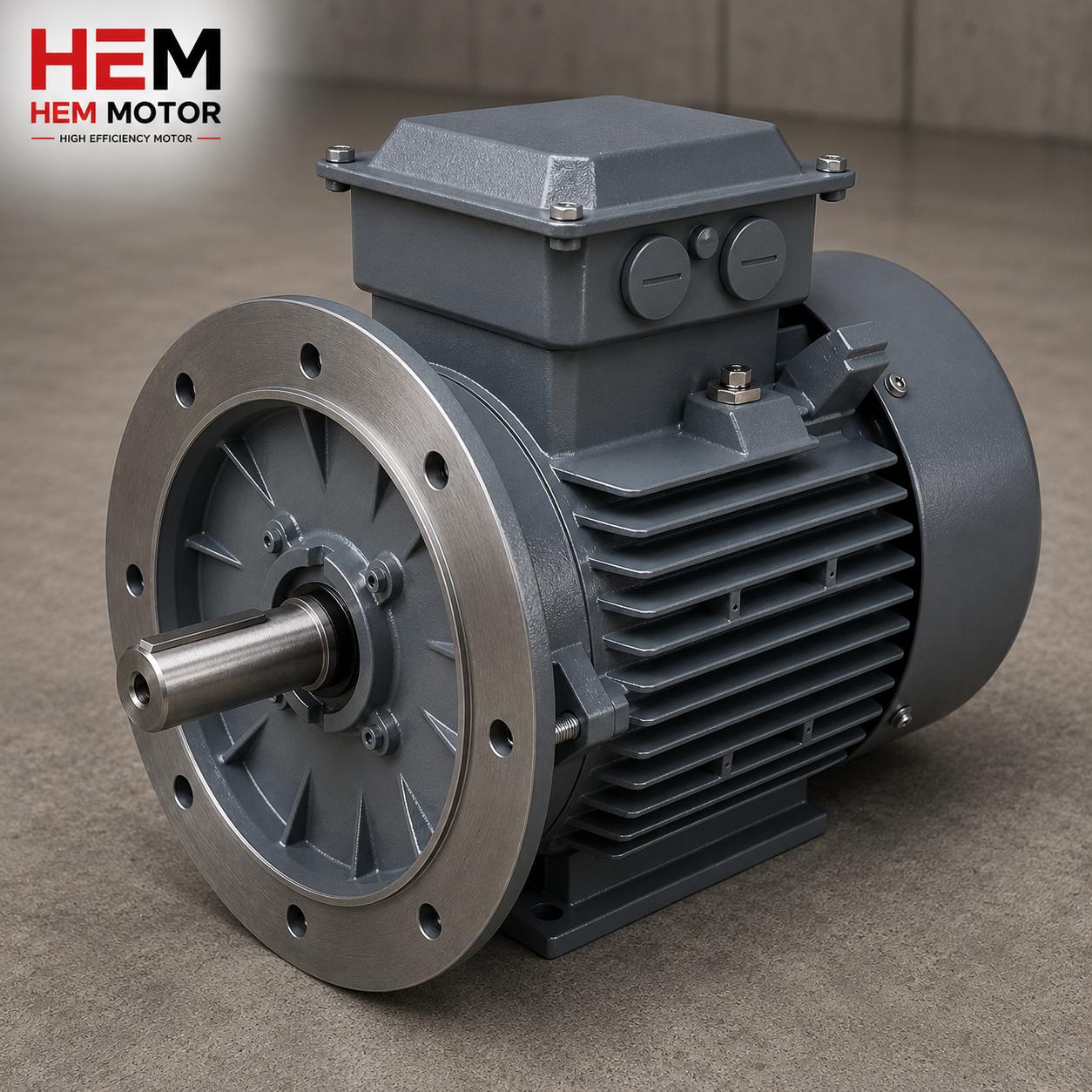
With a SynRM motor, the safest route is to procure the motor and drive as a properly matched package. As HEM Motor, we supply IE5 SynRM motors together with a drive prepared at the correct power and with the correct parameter set, from stock with fast delivery and manufacturer assurance. This way auto-tune completes smoothly on the first attempt in the field, commissioning time is shortened, and the risk of mismatch is eliminated. For the right power, mounting (B3, B5, B14, B35), and protection class (IP55, IP65/IP66 on request) selection, you can request a quote and get information about current electric motor prices.
Frequently Asked Questions
Will a SynRM motor run without auto-tune?
In practice, no. Without knowing the Rs, Ld, Lq, and saliency parameters, the drive cannot produce correct torque; without auto-tune the motor vibrates, fails to start, or trips on overcurrent. A correct motor identification is the first condition of commissioning.
Can static tune be done under load?
Yes. Since the rotor does not turn during static (standstill) tune, the motor can remain connected to the load; this method is preferred for motors whose coupling cannot be removed or that are connected to a pump or gearbox. For the most precise result, rotating tune with the load decoupled is recommended.
What happens if I select asynchronous as the motor type in the drive?
Because there is no slip current in a SynRM rotor, the drive uses the wrong model in asynchronous mode; the motor fails to start, oscillates, or gives an overcurrent fault. The motor type must be set to SynRM / reluctance mode and before auto-tune.


