English
 Türkçe

When selecting an IE4 motor, most engineers and buyers first evaluate the power rating, speed, mounting type (B3, B5, B14) and efficiency class. These are, of course, the right starting points. But once the motor arrives on site, gets mounted next to the panel or on the machine frame, and reaches the wiring stage, a frequently overlooked detail comes into play: the terminal (junction) box position and the cable entry direction. This seemingly minor detail directly determines how cleanly the motor fits your panel and cable route. A terminal box facing the wrong way can extend installation by hours, require extra cable glands and conduit, and worst of all, put the IP protection rating at risk.
In this article we examine in detail why the terminal box position and cable entry direction matter so much on IE4 motors, how to choose correctly based on your panel side, and which information you should provide at the ordering stage. Our goal is to help you commission your high-efficiency motor cleanly, safely and to standard on the very first try. Choosing the right motor in the right configuration reduces both installation time and total cost.
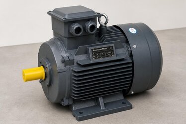
What Is a Terminal (Junction) Box and Why Does Its Position Matter?
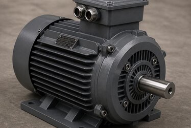
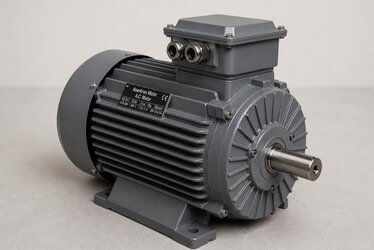
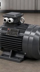
The terminal box, also called the junction box, is the enclosure where the motor's supply cables are connected and where the winding ends are brought out to the external world via terminal bridges (star/delta). On standard induction motors this box usually sits on the top of the motor frame, but depending on the manufacturer and model it can also be positioned on the right or left side. On IE4 premium efficiency motors, the frame design, the layout of the cooling fins and the bulkier winding structure can make the terminal box position and its internal working space differ from standard IE1/IE2 motors.
The terminal box position is not merely an aesthetic choice. It is critical for these three core reasons:
- Cable route compatibility: Whichever side the panel sits on, the cable is expected to reach the box by the shortest and tidiest path. A box facing the wrong way forces the cable to wrap around the motor.
- Preserving the IP protection rating: When the cable entry glands are not facing the right way, the sealing performance against water and dust ingress can degrade. A downward-facing entry is generally the safest against rain and condensation.
- Maintenance and access: Reaching the terminal bridges, temperature sensor and thermistor leads is far easier when the box position is chosen correctly. A box facing left in a narrow recess becomes a serious headache during maintenance.
Clock-Position Logic: Defining the Box Location
In the motor industry, the terminal box position is usually defined using clock-position logic, viewed from the motor's shaft (D-end). The standard location is most often considered "top." In IEC standards and manufacturer catalogues, positions are stated as: box on top, box on the right (right when viewed from the shaft end), box on the left. Some manufacturers use abbreviations such as "TE" (top entry), "RE" (right entry), or a clock position (for example "box on top, entry at 6 o'clock").
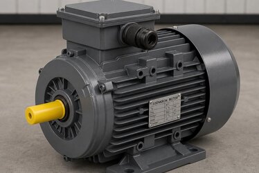
There are two distinct but interrelated parameters here: the position of the box on the frame (top/right/left) and the direction of the cable entry holes (entry facing down, to the side, or to the rear). A box may sit on top of the frame, yet the cable entry can be rotated to face down, right, left or rearward. On most modern IE4 motors the terminal box is designed to rotate in 4 x 90-degree steps, meaning it may be possible to turn the box to four different orientations with or without removing it. Even so, this flexibility is not always guaranteed, and a factory-set correct configuration is always the soundest solution.
Choosing the Right Box Position Based on Your Panel Side
The core logic of the right choice is simple: the cable should reach the terminal box from the motor surface on the panel side by the shortest, tidiest path. To clarify this, evaluate the on-site layout with these questions:
- Will the panel sit to the right, left, behind or above the motor?
- From which level does the cable tray arrive; does it drop from above or rise from the floor?
- Will the motor be mounted horizontally (foot-mounted B3) or vertically (flanged, shaft up/down)?
- How much clearance is there around the motor for maintenance; from which side can the box be comfortably accessed?
Typical Scenarios in Horizontal Mounting (Foot-Mounted B3)
On a horizontally mounted, foot-mounted motor the most common solution is to have the terminal box on top. In this case the cable entry is usually set to face downward or to the side. If the panel is on the motor's right, having the cable entry face right; if on the left, having it face left, lets the cable enter the box from the tray without unnecessary turns. For a cable tray arriving from below, a downward (6 o'clock) entry direction is both the tidiest and the safest against water ingress, because condensation cannot easily enter through the gland.
What to Watch in Vertical Mounting (Flanged V1/V3)
In vertical mounting, frequently encountered in pump applications (shaft-down V1 or shaft-up V3 position), the terminal box position becomes even more critical. On a vertical motor, a box left on top with the cable entry facing upward creates a risk of water pooling on the gland and weakens the IP protection. For this reason, in vertical applications it is preferable to position the box on the side with the entry facing down or sideways. When selecting an IE4 motor for pump, fan and compressor applications, this detail should be considered with particular care; we also cover this in our IE4 threshold in pumps, fans and compressors content.
The Cost of Choosing the Wrong Orientation: What Happens in Practice?
When the box position and entry direction arrive wrong, the problems on site are far costlier than they appear. Here are the most common issues:
- Unnecessary cable routing: To reach a box facing the wrong side, the cable must wrap around the motor. This means extra cable length, additional bends and a messier appearance.
- Extra glands and conduit: In some cases additional junction boxes, elbows and extra cable glands are needed to bring the cable to the correct angle, increasing material and labour cost.
- Risking the IP protection: A cable entry facing upward, or a gland that cannot be properly tightened, can allow water and dust into the box. This effectively voids a protection rating such as IP55/IP65.
- Forced box rotation on site: If the box is the rotatable type, it can be opened and turned on site, but this operation can affect the motor warranty and seal integrity; doing it in the rain or in a tight recess is also extremely difficult.
- Commissioning delays: Worst of all, if a wrongly configured motor has to be returned or replaced, the project loses days.
All these problems can be entirely prevented by sharing the correct information at the ordering stage. During the IE4 premium motor supply process, while preserving the advantage of fast delivery from stock, we clarify these details with our customers from the very beginning to ensure the configuration is correct too. Our guide on IE4 premium motor supply, stock and lead time will be a helpful reference.
Information to Specify Correctly When Ordering
When ordering an IE4 motor, clearly specifying the following terminal box and cable entry details ensures the motor arrives correct on the first try:
- Mounting type: B3 (foot), B5 (flange), B14 (face flange) or a combination. The mounting type also affects the position of the box and shaft relative to the frame.
- Operating position: Horizontal or vertical (shaft up/down)? IEC mounting position codes such as IM B3, IM V1, IM V3 give the most precise definition.
- Terminal box position: Should it be on top, right or left when viewed from the shaft end?
- Cable entry direction: Should the entry face down (6 o'clock), up, right or left? Downward entry is generally the safe default.
- Cable entry diameter and gland type: The appropriate gland (M or PG thread) should be chosen according to the cable cross-section and quantity.
- IP protection rating: A protection rating such as IP55 or IP65 should be specified according to the environmental conditions (dust, humidity, outdoor) of the application.
- Additional accessories: If there are extra leads such as PTC thermistors, PT100 sensors or anti-condensation heaters, remember that these require adequate space in the terminal box.
Sharing this information with a single shaft-end / entry-direction sketch is the soundest method. Even a simple hand drawing prevents misunderstandings and ensures the motor arrives matching your panel exactly.
The Shaft-End Reference: The Key to Avoiding Confusion
The biggest confusion in the right-left definition stems from the question "right according to whom?" The industry standard convention is to define right and left when looking toward the motor from the main shaft (D-end). Always clarify this reference in the order: "viewed from the shaft end, the terminal box on the right, cable entry facing down." This clarity reduces errors to zero during manufacturing or stock selection. You can also find the technical fundamentals of choosing the right motor on our IE4 high-efficiency electric motors page.
IP Protection, Condensation and Cable Entry Direction
The relationship between cable entry direction and IP protection is often underestimated. Entering the cable from the bottom face of the terminal box, that is, from downward-facing glands, is the safest solution against both external water and condensation that may form inside the box. An upward-facing gland can come into direct contact with rain or wash-down water, and over time, as the seal fatigues, water can seep inside. A side entry carries medium-level risk and is generally acceptable in indoor applications.
In humid or aggressive environments such as outdoor, food plants (wash-down), textiles, paper and chemicals, the entry direction should be planned just as carefully as the IP rating. A downward entry, together with a properly tightened gland and a correctly sized cable gland, provides a safe connection throughout the motor's life. These details also affect the motor's total cost of ownership; a correct start is essential to reduce fault and maintenance costs.
Features of Terminal Box Design on IE4 Motors
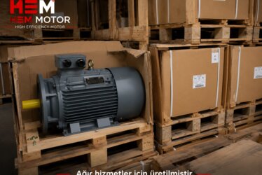
IE4 premium efficiency motors contain more copper and a more optimized winding design to produce lower losses. On some models this can affect the frame size and the internal volume of the terminal box. Larger-section supply cables, more auxiliary leads (sensors, thermistors) and the need for a larger bending radius require the in-box working area to be planned correctly. On a well-designed IE4 motor, the terminal box has both adequate internal volume and a rotatable cover structure, which increases wiring flexibility.
The high-efficiency IE4 motors we offer are supplied to suit different mounting and wiring scenarios. We help you select a motor in the right configuration from our stock and, when needed, clarify your box position and entry direction preferences from the very beginning. You can review our full product range and technical support through our homepage, and together determine the most suitable motor for your project.
A Practical Checklist
Reviewing this short list before ordering eliminates any surprises during installation:
- I have determined the panel's position relative to the motor (right/left/rear/top).
- I have noted from which level the cable tray arrives (up/down).
- I have defined the mounting position (B3 horizontal / V1-V3 vertical) with the IEC code.
- I have defined the terminal box position using the shaft-end reference.
- I have specified the cable entry direction (preferably down) and the gland type.
- I have chosen the IP rating suited to the environmental conditions.
- I have accounted for extra leads such as sensors/thermistors requiring space in the box.
By following this checklist, the IE4 motor you select connects to your panel cleanly and safely on the first try. The right configuration lets you benefit fully from both the energy-efficiency advantage and a fast, trouble-free installation process.
Frequently Asked Questions
Can I change the terminal box orientation myself on site on an IE4 motor?
On many modern IE4 motors the terminal box is designed to rotate in 4 x 90-degree steps, and it may be possible to remove the cover and turn the box to a different orientation. However, this operation can affect seal integrity, IP protection and, in some cases, the warranty. Moreover, doing it in a tight recess or outdoors is both difficult and risky. The soundest method is to determine the correct position and entry direction at the factory or during stock selection. When you specify the position clearly in the order, no rotation is needed on site at all.
Why should I choose a downward cable entry where possible?
A downward (6 o'clock) cable entry is the safest solution against both external water (rain, wash-down) and condensation that may form inside the box. Upward-facing glands can, over time, create a path for water to seep inside and effectively lower the IP protection rating. A downward entry also aligns with the cable's natural drooping direction, providing a tidier, stress-free connection. Especially in humid, dusty or outdoor applications, downward entry is a strong default choice.
How should I clearly specify the terminal box position when ordering?
The safest method is to define the position when looking toward the motor from the main shaft (D) end. For example, a single clear sentence such as "viewed from the shaft end, terminal box on the right, cable entry facing down" is sufficient. If you add the mounting type (B3, B5, etc.), operating position (horizontal/vertical) and IP protection rating to this, the motor will arrive matching your panel exactly. Adding a simple hand sketch fully eliminates misunderstandings and guarantees the correct motor arrives on the first try.