English
 Türkçe

Summary (TL;DR)
- A rotary airlock (also called a cellular feeder or vane feeder) is the drive element that sits under the baghouse or cyclone dust collector in crusher and mining plants, continuously discharging collected dust without letting pressure leak; its rotor turns at very low speed (typically in the tens of RPM).
- This low output speed and high torque cannot be obtained directly from a 1500 rpm motor, so the motor must always be selected as a geared motor, paired with a reducer (worm gear or helical-bevel).
- The airlock runs as long as the plant runs: the motor must be rated for S1 continuous duty, with high starting torque, thermal protection and a torque margin against jamming.
- The heavy, abrasive dust environment demands IP55 (IP65/IP66 on request), a cast iron body, F insulation, shaft oil seal / V-ring sealing and a dust-resistant fan cowl.
- Airlock drives are mostly in the small power class (0.37–2.2 kW); with HEM Motor mining/crusher motors and HEM40–HEM130 worm gear reducers you can supply the right motor + reducer combination from stock.
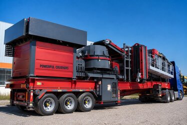
Dedusting systems are indispensable in crusher and mineral processing plants. Wherever stone is crushed, screened and conveyed, fine dust is released; this dust is captured in baghouse dust collectors or cyclones. The captured dust must be removed from under the filter hopper without disturbing the negative or positive pressure of the system. This is exactly where the rotary airlock (also known in the field as a cellular feeder or vane feeder) comes in. In this article we cover, from an engineering perspective, how to select the airlock drive motor: why it must be geared, which protection class, body, insulation and sealing features it needs, and how to buy the right motor + reducer combination.
What Is a Rotary Airlock and Why Is the Drive Motor Critical?
A rotary airlock consists of a rotor that turns inside a cylindrical housing, with radial vanes arranged around it. The cells formed by the vanes fill with material from the top, are carried to the bottom as the rotor turns, and are emptied. While this happens, the successive vanes maintain a continuous air barrier (lock) between the top and the bottom, so the pressure in the filter hopper is not lost while dust is discharged, nor does false air leak inward. In other words, the airlock does two jobs at once: it discharges the dust and seals the pressure.
This dual task directly affects the selection of the drive motor. For the airlock to perform its function, the rotor must turn smoothly and with high torque, at very low speed and in a continuous duty regime. If the rotor turns too fast the cells cannot fill and empty fully, sealing weakens and wear increases; if it turns too slowly the discharge capacity cannot keep up with the plant's dust production. Motor selection is therefore tightly coupled with capacity calculation and speed control.
Why Does the Airlock Rotor Turn So Slowly?
A typical cellular feeder rotor turns in the range of roughly 10–40 RPM depending on the application. Even in some high-capacity discharges where this value is a little higher, the speed almost never approaches the 1500 rpm nominal speed of a standard asynchronous motor. The low speed is driven both by sealing (the vanes must pass the seating surface slowly) and by wear control: the rotor tips run within tight tolerance to the housing, and fast rotation together with abrasive mineral dust causes early wear.
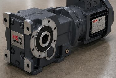
Why Is a Geared Motor Essential?
The slowest common speed of a standard three-phase asynchronous motor is around 1500 rpm in the 4-pole version (~1000 at 6 poles, ~750 rpm at 8 poles). It is impossible to reach the tens-of-RPM speed the airlock needs directly with these motors. Moreover, high torque is required at low speed; reducing speed while keeping power constant means increasing torque. The correct and economical way to provide this is to use a standard 1500 rpm motor together with a reducer.
In airlock drives the most frequently preferred solution is to mount the motor directly to a worm gear reducer with a B5 or B14 flange. The worm gear reducer, with its compact structure, right-angle output shaft and high reduction ratio, is very well suited to this application. In a sample calculation, a 1500 rpm input is stepped down by a ratio between 1/30 and 1/100 to obtain 15–50 RPM at the rotor. Plants requiring higher efficiency and precision may prefer helical-bevel (K series) reducers, which offer higher efficiency and lower oil heating.
- Input speed: 1500 rpm (4-pole standard motor) is the most common choice; for very low output, a 6/8-pole motor can be combined with a smaller reduction ratio.
- Reduction ratio: between 1/7.5 and 1/100; selected according to the required rotor speed.
- Mounting: mounting the motor to the reducer input with B5 (large flange) or B14 (small flange) eliminates the trouble of intermediate couplings and alignment.
- Power class: the 0.37–2.2 kW range is very common in airlock drives; in large plants it can rise to 3–4 kW.
To correctly establish the output speed and torque relationship in a geared motor, before purchasing we recommend reviewing our monoblock geared motor purchasing: output speed and torque guide, where you can find reduction ratio, output torque and service factor calculations step by step.
S1 Continuous Duty and High Starting Torque
A crusher plant runs throughout the shift; the dust collection system, and therefore the airlock, also turns nonstop during this time. For this reason the drive motor must absolutely be sized for S1 continuous duty. A cheaper motor selected for an intermittent (S3) regime will overheat under continuous load and its winding life will be shortened.
Another critical issue in the airlock is the starting and jamming torque. Fine dust from the filter, especially when moist or oily, can clump in the cells, form a bridge (bridging), or jam between the vane and the housing. When the plant stops and restarts, the first movement of the rotor loaded with full cells requires high starting torque. The service factor of the motor and reducer must be selected to handle this sudden load.
Jam and Foreign Object Protection
Small stone fragments or foreign objects can occasionally mix into the mineral dust. These can get between the rotor and the housing and lock the rotor (stall). In such a case the motor stops but keeps drawing current; an unprotected motor will burn its winding. Therefore:
- The motor should be selected with a certain margin over its nominal torque (via the service factor).
- Thermal protection embedded in the winding (PTC thermistor or thermal klixon) should provide shutdown at the moment of overheating.
- In airlocks driven by a VFD, current/torque limit and jam detection parameters should be activated.
- On the reducer side, mechanical protections such as a torque limiting (slip) clutch or shear pin can be considered.
In plants requiring speed control, the speed is adjusted with a frequency inverter; this way the rotor speed is optimized according to dust flow and full torque is maintained even at low speed (a force-cooled motor is selected if needed).
Dusty and Abrasive Environment: Protection Class, Body and Sealing
The environment in which the airlock operates presents one of the most demanding conditions for an electric motor: fine, abrasive mineral dust continuously suspended in the air. This dust tries to seep in through the smallest opening of the motor, sticks to the fan and fan cowl, and works its way along the shaft outlet toward the bearings. A motor that is not correctly specified will quickly suffer bearing and winding failure due to dust.
Protection Class (IP) Selection
A minimum of IP55 is recommended for the airlock drive motor: not total dust protection, but a class that prevents harmful levels of dust ingress and is resistant to water jets. Especially on lines that are wash-cleaned or where dust is very heavy, it is right to upgrade to IP65/IP66; in these classes dust ingress is completely prevented. HEM Motor offers IP55 in standard production and IP65/IP66 on request.
Body, Insulation and Winding
- Cast iron body: far more resistant than aluminum to the impact, vibration and thermal loads of the mining environment; high mechanical strength and heat dissipation.
- Class F insulation: provides a high temperature margin, extends winding life under continuous load.
- 100% copper winding: low loss, high efficiency and lower heating in continuous operation.
- Reinforced bearings: extend life for dusty/heavy use.
Shaft Sealing and Fan Cowl
To prevent abrasive dust from reaching the bearings, a quality shaft oil seal and, where needed, an additional V-ring seal should be used at the shaft outlet. To go deeper on this topic, see our shaft oil seal and V-ring selection for dusty environments article. On the fan side, a fan cowl with a textile / anti-dust guard that prevents dust accumulation and clogging should be preferred; for details, the fan cowl and guard selection for dusty environments guide will be useful. If the fan cowl clogs with dust, the motor cannot cool and the winding temperature rises to a dangerous level.
Step-by-Step Motor + Reducer Selection
The logic to follow when choosing the right combination for the airlock drive is as follows:
- 1. Determine the rotor speed: based on dust discharge capacity and cell volume, set the required output speed (e.g. 20 RPM).
- 2. Calculate the output torque: determine the rotor's starting and continuous duty torque, adding a jamming margin.
- 3. Select the reduction ratio: determine the ratio (e.g. 1/75) that steps down the 1500 rpm input to the required output speed.
- 4. Choose the reducer type: worm gear for a compact, right-angle solution; helical-bevel for high efficiency.
- 5. Choose the motor power and pole count: select the power that meets the output torque and service factor (e.g. 0.55–1.5 kW) and the 4-pole (1500 rpm) standard.
- 6. Define the protection and sealing package: IP55/IP65, cast iron, F insulation, oil seal/V-ring, dust-resistant fan cowl, thermal protection.
The HEM Motor product range includes solutions that meet all of these steps. You can review our motors designed for mining and crusher applications on the mining sector electric motor page, and the reducers ideal for airlocks on the worm gear reducers page.
Airlock Drive with the HEM Motor Product Range
HEM Motor electric motors are designed in the IE3/IE4 efficiency class, in the 0.25–355 kW power range, at 1000/1500/3000 rpm standard speeds (and with 6/8-pole options for low speed), with a cast iron body, IP55 (IP65/IP66 on request), F insulation, 100% copper winding and for S1 continuous duty. Thanks to B3/B5/B14/B35 mounting options, direct flange mounting to the reducer is easy.
Our worm gear reducers suited to airlock power classes:
- HEM40: 0.12–0.37 kW
- HEM50: 0.18–0.75 kW
- HEM63: 0.37–1.5 kW
- HEM75: 0.75–3 kW
- HEM110: 2.2–7.5 kW
- HEM130: 4–11 kW
All reducers are supplied in the 1/7.5–1/100 ratio range with a B5/B14 IEC flange input. This way you can supply the motor + reducer pair needed for the airlock drive from a single source, compatibly, from stock. Helical-bevel (K series) reducers are also available for plants requiring high efficiency and low oil heating.
Frequently Asked Questions
How many kW of motor is needed for an airlock drive?
In most crusher/mining airlock applications the 0.37–2.2 kW range is sufficient; for high-capacity discharges it can rise to 3–4 kW. The correct power is calculated according to the rotor's starting and continuous duty torque, the jamming margin and the reducer efficiency. For an exact power figure, simply share the rotor diameter, cell volume and required output speed with us.
Why is a geared motor used instead of a directly low-speed motor?
Because even the lowest common speed of standard asynchronous motors (~750 rpm at 8 poles) is far higher than the tens-of-RPM speed the airlock needs, and producing the required high torque directly at low speed is not economical. Combining a standard 1500 rpm motor with a reducer both lowers the speed and increases the torque; it is more economical, compact and durable.
Which protection class should I choose in a dusty environment?
A minimum of IP55 is recommended. On lines where dust is very heavy or wash-cleaning is performed, it is right to upgrade to IP65/IP66. In addition, the choice of cast iron body, quality shaft oil seal/V-ring and dust-resistant fan cowl is at least as important as the IP class; these details determine the motor's real service life in a dusty environment.
For the right motor + reducer combination, pricing and stock information, you can reach us via our up-to-date electric motor prices page and get a quote tailored to your project.