English
 Türkçe
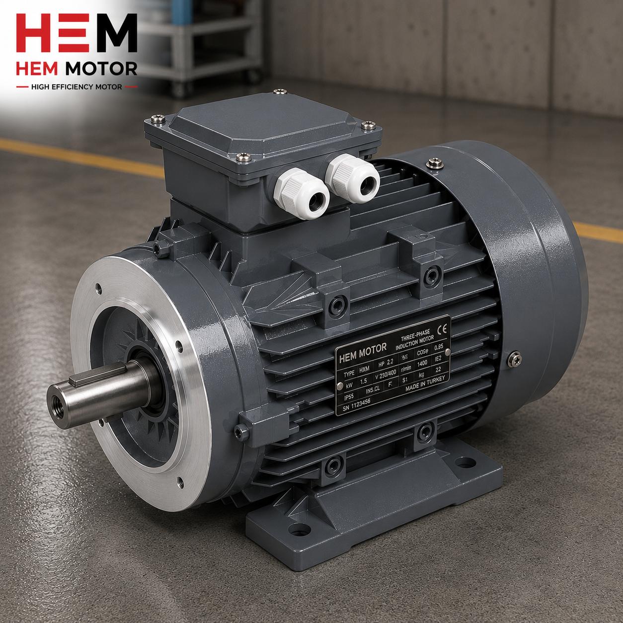
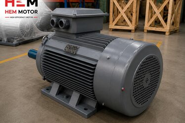
When you connect a cast iron electric motor by its flange to a pump, gearbox, fan or compressor, the invisible yet most critical step is the flange connection bolt torque. If the bolts are under-tightened, the joint loosens over time, runout (axial misalignment) grows, bearings die early and the oil seal leaks. If they are over-tightened, the flange cracks, the bolt shears or the spigot register deforms. In this article we explain the logic of B5/B14 flange matching, the correct bolt class, how torque values are determined, sealing and assembly sequence, and what to watch for at the purchasing stage, with examples from the field and an engineering perspective.
At HEM Motor we both manufacture and sell cast iron bodied motors, so we know the connection details not only from catalogs but also from the feedback of thousands of motors our customers fit to their machines. A correctly built flange connection is the silent hero that extends motor life, lowers vibration and minimizes maintenance cost.
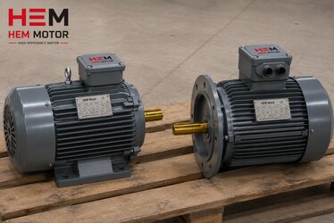
B5 and B14 Flanges: Two Different Connection Philosophies
Cast iron motors come with two basic flange types and the bolt logic of each is completely different. The B5 large flange uses a wide machined flange face on the motor end shield with clearance holes through the outside of the flange; the bolts pass from the motor side toward the machine and are secured by nuts or tapped holes on the other side. The B14 small flange is more compact and the bolts go directly into the tapped holes on the flange face; the bolt attaches to the machine housing not through the flange but from outside.
This difference directly affects tightening torque. On a B5 flange the bolt carries the tension load directly and larger diameter bolts are usually used. On a B14 flange the tapped hole is limited; if you apply excessive torque you strip the thread in the cast iron. That is why on B14 connections it is vital not to overdo torque and, if necessary, to choose a quality bolt with the correct thread for the tapped hole.
Flange Size Depends on Frame Size
- The IEC frame size (56, 63, 71, 80, 90, 100, 112, 132, 160 and above) determines the flange diameter, the bolt circle (pilot diameter) and the bolt count. The flange bolts of an 80 frame motor and a 160 frame motor are not the same.
- The pilot diameter (spigot/centering register) centers the motor to the machine. Bolts do not perform centering; they only provide axial retention. The centering register must be clean and undamaged.
- The bolt count is usually four; it may increase on large flanges. All bolts must be tightened in a crosswise sequence and in stages.
The choice between B5 and B14 is made by the machine builder; our guide on B5 versus B14 motor mounting type selection, which we examine from a purchasing angle, helps you decide before ordering.
Bolt Class and Torque: Where Do the Numbers Come From?
The tightening torque of a flange bolt depends on three things: the bolt's diameter and thread pitch (M8, M10, M12, M16), the bolt's strength class (8.8, 10.9, 12.9) and the joint's friction coefficient (lubricated or dry). The same M12 bolt requires very different torque in class 8.8 versus class 10.9. So using a field rule of thumb like "if it is M12 then this many Nm" is wrong; the bolt class must always be known.
- Class 8.8 bolts are sufficient for the majority of standard industrial connections and are the most common choice for flange joints.
- Class 10.9 and 12.9 are preferred in high vibration, high torque transmitting or heavy duty applications. Torque is higher in these classes, but the limit the cast iron thread can bear must be respected.
- Galvanized, stainless or lubricated bolts have different friction than a dry bolt. The same torque value creates higher preload on a lubricated bolt; therefore the assembly instruction must state the lubricated/dry condition.
Preload Logic: Torque Is Actually a Result
The purpose of bolt tightening is to create sufficient preload (clamping force) between the flange faces. This force prevents the joint from loosening under the vibration and axial thrust that occur during operation. Torque is a practical tool that indirectly measures this preload. Ideally the manufacturer's torque value is applied with a calibrated torque wrench. The "I tightened it hard with arm strength" approach either under or over tightens the joint, and both sow the seed of failure.
Correct Assembly Sequence: Step by Step
When done in the right order, the flange connection of a cast iron motor guarantees both sealing and concentricity. The practical steps we follow in the field are:
- Surface cleaning: The flange face, the centering register and the mating surface are cleared of burrs, old gasket residue and dust/chips. Small casting burrs on the cast iron must be deburred.
- Centering: The motor flange is seated into the machine's pilot register without forcing. Hammering it in crushes the centering register.
- Starting the bolts by hand: All bolts are first seated by hand or at low torque. Fully tightening one bolt before moving to the next warps the flange.
- Cross staged tightening: The bolts are tightened in a star (crosswise) sequence, first to about half the torque, then to the full value. This distributes the load evenly.
- Concentricity check: On coupled connections the axial and angular misalignment is measured with a laser or dial gauge. After the flange is tightened the shaft must turn freely without binding.
- Check after first run: After a few hours of operation the torque is rechecked; a small loosening during the initial seating is normal.
Coupling and key fit on the shaft side are at least as important as the flange. Our in-depth guide on shaft diameter, key and coupling matching on cast iron motors shows how the flange and the mechanical side must be aligned as a whole.
Sealing: Preventing Oil and Dust Leaks Through the Flange
The flange connection is not only a mechanical hold; it is also a sealing interface. Especially on a motor connected to a gearbox or an oily machine, oil leaking through the flange face or dust entering from outside causes serious problems.
- Surface flatness: The machined face of the cast iron flange must be smooth and burr free. A warped or scratched surface leaks no matter how tightly the bolts are torqued.
- Gasket and sealant: On oily connections an appropriate gasket or liquid sealant is used between flanges. The gasket type is specified by the machine builder.
- Oil seal coordination: The oil seal at the motor shaft exit is the second barrier against oil coming from the flange. In dusty and oily environments seal choice is critical, a topic we cover in our article on oil seal and sealing protection on cast iron motors.
- IP protection integrity: Flange and terminal box sealing determine whether the IP55/IP65 protection on the nameplate is actually achieved in the field. We recommend also reading about one link of this chain in motor terminal box and cable connection, IP protection and correct gland selection.
Common Mistakes and Their Consequences
- Over-tightening: Strips the thread in the cast iron, cracks the flange or deforms the centering register. The crack is often invisible at first and grows with operation.
- Under-tightening: The bolt loosens with vibration, runout grows, the coupling wears and the bearing ends early.
- Tightening one by one (not crosswise): The flange warps and concentricity is lost.
- Wrong bolt class: Using a low strength bolt instead of 8.8 leads to shearing under vibration.
- Uncalibrated torque wrench: Even if you apply the right number, the result is wrong if the tool is faulty.
Correct Stock and Supply at the Purchasing Stage
A correctly built flange connection starts with the correct motor. Clearly stating the mounting type (B5/B35/B14), frame size, shaft diameter and flange dimensions when ordering is the key to avoiding mismatches in the field. At HEM Motor we offer cast iron bodied motors from stock across a wide power and frame range and deliver them with the correct flange dimensions. For current electric motor prices and stock availability you can contact us.
When the right bolt class, the right torque and the right assembly sequence come together, your cast iron motor runs vibration free and leak free for decades. Neglecting any one of these three drives even the highest quality motor into early failure.
Notes from the Field and a Quick Checklist
The problems we most frequently encounter in the field with the flange connection of cast iron motors actually stem from simple but overlooked details. The checklist below is a practical summary you can quickly review before and after assembly; even experienced teams can skip these steps under time pressure, and the result is early failure.
- Inspect the flange face by eye and by hand: If there are burrs, scratches, old gasket residue or impact marks, clean them; smooth them with fine abrasive if needed. A rough surface leaks even at the correct torque.
- Protect the centering register: Do not hammer the motor into the machine; if the pilot diameter is forced it gets crushed and never centers properly again. Lightly oiling the register makes seating easier.
- Verify the bolt class and length: A short bolt does not engage enough thread, a long bolt bottoms out and creates the wrong preload. Always know whether it is 8.8 or 10.9.
- Calibrate the torque wrench: Calibration at least once a year is a precondition for applying the right number.
- Tighten crosswise in two stages: First half torque, then full torque; full tightening in one pass warps the flange.
- Recheck after the first run: After a few hours of operation, recheck the bolts; a small loosening during the initial seating is normal.
- Monitor vibration and temperature: If the connection is correct the motor runs vibration free and without overheating; abnormal vibration points to a concentricity or loosening problem.
These simple steps keep the flange connection of your cast iron motor trouble free for years. A correctly built connection reduces the workload of your maintenance team and largely prevents unplanned stoppages. Clearly stating the correct mounting type and dimensions at the ordering stage is the first and most important link in this chain.
Frequently Asked Questions
Can I fit a B5 flanged motor into B14 holes?
No. B5 and B14 flanges differ in diameter, bolt circle and connection logic; B5 connects with external clearance holes, B14 with tapped holes on its face. An adapter flange can be used but direct interchange is not possible. It is best to clarify your machine's flange type before ordering.
How tight should I make the flange bolts?
The correct torque depends on the bolt diameter (M8, M10, M12...), strength class (8.8, 10.9) and lubricated/dry condition. Rather than giving a single number, apply the torque table from the motor and machine manufacturer with a calibrated torque wrench. What matters is balanced preload, which you achieve with cross staged tightening.
Why does oil leak from the flange and how is it prevented?
It is usually caused by surface unevenness, a missing/wrong gasket, a loose bolt or a worn oil seal. Keeping the flange face clean and flat, using a suitable gasket, tightening bolts to the correct torque and keeping the shaft seal intact prevent leaks.