English
 Türkçe
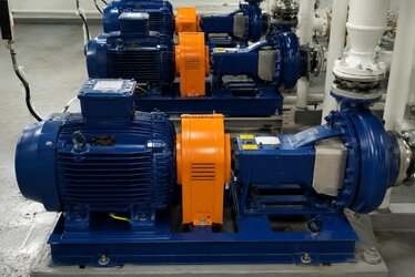
One of the most common issues when commissioning a new pump motor or fan motor — or restarting a motor after maintenance or rewinding — is the motor running in the wrong direction, or reverse rotation. Three-phase asynchronous motors rotate clockwise or counter-clockwise depending on the phase sequence they are connected to; swapping any two phases reverses the direction of rotation. In centrifugal pumps this does not necessarily mean the pump produces no pressure at all — the pump may still build some head, which misleads the operator — but flow drops sharply, efficiency collapses, and the system fails to deliver its rated performance. In fans, airflow is greatly reduced, the motor may draw abnormal current, and energy is wasted.
This article covers phase sequence, rotation direction verification, the check valve (non-return valve) and backflow problem, mistakes made in star-delta (Y/Δ) wiring, and the correct terminal box connection step by step for three-phase pump and fan motors. The goal is to help you safely confirm rotation direction before the first start and to prevent these problems from the outset by using correctly labelled, factory-tested motors.
How Is Rotation Direction Determined in a Three-Phase Motor?
The rotation direction of a three-phase asynchronous motor is set by the direction of the rotating magnetic field created in the stator windings. This field depends on the time sequence of the three phases (L1, L2, L3) coming from the grid. When the phase sequence is correct, the field rotates in one direction; if any two phases are swapped, the field — and therefore the rotor — rotates in the opposite direction. For this reason, the fix for reverse rotation is usually very simple: swap two of the phase cables in the terminal box.
However, this simplicity does not reduce the importance of the issue. Especially in centrifugal pumps and axial fans, the wrong rotation direction causes both performance loss and mechanical stress. In a pump you may see cavitation, overheating and seal wear; in a fan, insufficient airflow, vibration and shortened bearing life. Therefore rotation direction must always be verified before coupling the motor to the load.
Phase Sequence and the Magnetic Field
In a standard grid, phases arrive in the order L1-L2-L3, spaced 120 degrees apart. When connected to the motor's U-V-W terminals in this order, the rotating field turns in the design direction (usually clockwise when viewed from the shaft end). When two phases are swapped — for example V and W — the field reverses. A phase sequence meter (phase sequence relay or handheld indicator) lets you measure the grid sequence in advance, which is practical for maintaining a standard where multiple motors are fed from the same panel.
Nameplate and Direction Arrow
Most fan and pump motors have a direction arrow on the fan cowl or frame indicating the intended rotation. Before the first start, check this arrow; when you run the motor, the shaft must turn in the arrow's direction. On correctly labelled, factory-tested motors these markings are clear and the U1-V1-W1 / U2-V2-W2 terminals are in standard positions, which simplifies field wiring.
Verifying Rotation Direction Before Commissioning
Verifying rotation while the pump/fan is uncoupled from the load is the safest method. The steps applied in practice are:
- Bump test (short jog): Run and stop the motor very briefly without the load, or with the coupling disconnected, and observe which way the shaft turns.
- Compare with the arrow: Compare the observed direction with the rotation arrow on the fan cowl or frame.
- Phase sequence indicator: Measure the supply phase sequence at the panel with a handheld device and lock it to a standard order.
- Closed-valve check on pumps: If the pressure measured with the discharge valve closed is far below expected, reverse rotation is likely.
- Current observation: Under the same load, reverse rotation usually shows a different current profile (often low-flow, high-slip behaviour).
If the rotation is wrong, the solution is to swap two phase cables at the panel or terminal box. Shifting all three phases does not change direction; only swapping two phases reverses it. In systems driven by a variable frequency drive (VFD), the direction can also be changed via a drive parameter, so no cable change is needed. To explore phase sequence and rotation direction in more depth, our guide on motor rotation direction and phase sequence details the ordering and commissioning steps.
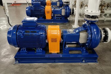
Effects of Reverse Rotation in a Centrifugal Pump
In centrifugal pumps the impeller is designed to turn in a specific direction. During reverse rotation the impeller still throws fluid outward, so the pump may continue to produce some pressure — and this misleads the user. But actual flow and efficiency drop sharply. Typical symptoms:
- Much lower flow and head than expected.
- The motor failing to reach rated power or drawing unexpected current.
- Noise, vibration and premature seal wear.
- In some pumps, a risk of the impeller nut loosening (reverse rotation can drive the impeller in the unscrewing direction).
For correct pump motor selection and speed matching, we recommend the guide on centrifugal pump motor selection: flow and head. When the correct impeller direction, correct speed and correct power come together, the system delivers its rated performance.
Check Valve and the Backflow Problem
A check valve (non-return valve) allows fluid to pass in only one direction and prevents backflow when the pump stops or runs the wrong way. When the pump stops, the water column in the discharge line tries to return under gravity; the check valve cuts this backflow, preventing the pump from draining and the suction side from losing prime. It also limits sudden pressure surges (water hammer), protecting the pipeline and the pump.
If the motor runs in reverse rotation, the water hammer and backflow risks in the system change. At low flow or in reverse operation the check valve's opening-closing behaviour can be disrupted, the valve may chatter, and both the valve and pipe connections are stressed. Therefore, alongside check valve selection and mounting orientation, it is vital that the motor driving the pump turns in the correct direction.
Water Hammer and Bearing Load
When a pump stops suddenly or a check valve closes quickly, the resulting pressure wave can reflect into the pipeline and indirectly onto the motor shaft. Repeated water hammer events add dynamic load on the coupling and bearings. When correct rotation direction, soft starting (soft starter or star-delta) and proper check valve selection are addressed together, these loads are kept under control and motor life is extended.
Mistakes Made in Star-Delta (Y/Δ) Wiring
In high-power pump and fan motors, star-delta starting is often used to reduce starting current. The motor first starts in star (Y) at reduced voltage, then transitions to delta (Δ) once speed builds. The bridges in the terminal box (U1-V1-W1 and U2-V2-W2) and the contactor connections enable this transition.
Common Y/Δ Mistakes
- Wrong bridging: Mixing up the star and delta bridges makes the motor run at the wrong voltage and overstresses the winding.
- Phase sequence changing at delta transition: If phase connections get mixed during the changeover, this can cause reverse rotation or sudden torque shocks.
- Incorrect timer setting: Switching from star to delta too early produces a high current surge.
- Mislabelled terminals: On rewound motors, if the U2-V2-W2 terminals are mislabelled, both direction and connection are corrupted.
To wire the star-delta scheme correctly, you can use the guide on how to make an electric motor star-delta wiring diagram. On correctly labelled, factory-tested motors the U1-V1-W1 / U2-V2-W2 terminals are in standard positions, making error-free bridging easier at the panel.
Correct Terminal Connection: U1-V1-W1 / U2-V2-W2
A three-phase motor's terminal box has six terminals: U1, V1, W1 (winding starts) and U2, V2, W2 (winding ends). The connection is bridged as star or delta according to the operating voltage. When the terminal connection is made without error, the motor runs at the correct voltage, with the correct torque and in the correct direction.
- Star (Y): U2-V2-W2 are bridged together; supply comes to U1-V1-W1. Lower starting current, lower starting torque.
- Delta (Δ): Each winding start is bridged to the next winding end (in the U1-W2, V1-U2, W1-V2 logic); supply comes to the bridge points. Full torque and full power.
The connection diagram on the nameplate shows at which voltage the motor is connected in Y or Δ. On correctly labelled motors this information is clear, so when ordering it is critical that the nameplate data (voltage, frequency, connection type, power, speed) is complete for error-free field wiring.
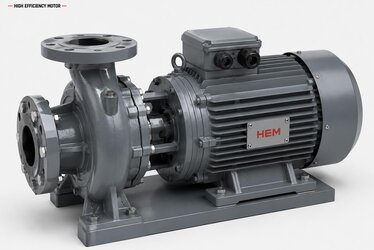
Preventing These Problems from the Start: Correct Motor Supply
Most of the reverse rotation, backflow and connection errors in the field stem from mislabelled motors or motors with unclear connection data. The motors HEM Motor manufactures and supplies from stock for pump and fan applications come with a clear rotation arrow, a standard U1-V1-W1 / U2-V2-W2 terminal layout, IP55 protection, Class F insulation and cast iron body options. They are available in IE3 and IE4 efficiency classes and in B3 foot-mounted, B5 and B14 flange and B35 combined mounting types.
- Factory tested: Every motor is checked for rotation direction and connection; no surprises in the field.
- Correct nameplate: Power, speed, voltage and connection diagram are clear; in the pump electric motors product group the right selection is made for the application.
- Delivery from stock: Frequently requested power-speed combinations are in stock; fast replacement for a failed motor.
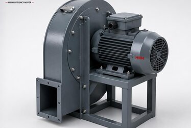
- Fan applications: For ventilation and exhaust, industrial fan motors are offered with the correct speed and mounting type.
Selecting a motor with the correct power, speed and mounting type saves time and cost during commissioning. For current models and electric motor prices, you can review our product groups.
Frequently Asked Questions
My pump builds pressure but the flow is low — is it running in reverse?
This is a classic symptom of reverse rotation in centrifugal pumps. With the impeller turning the wrong way it still produces some pressure, but flow and efficiency drop sharply. To check, uncouple the motor from the load and compare the rotation direction against the arrow with a short bump test. If the direction is wrong, swapping two phase cables at the terminal box or panel fixes it. After the change, measure flow and current again to confirm.
Why is a check valve necessary, and how does reverse rotation affect it?
A check valve prevents backflow and water hammer when the pump stops; it stops the water in the discharge line from returning and the pump from draining. If the motor runs in reverse or at very low flow, the check valve's opening-closing behaviour can be disrupted, the valve may chatter, and pipe connections are stressed. So both correct check valve selection and correct motor rotation must be ensured together.
The motor reverses during the star-delta transition — why?
The cause is usually incorrect phase connection or bridging during the star-delta transition. If the phase sequence is not preserved when switching to delta, reverse rotation or sudden torque shocks occur. The fix is to bridge the terminals (U1-V1-W1 / U2-V2-W2) correctly and to lock the phase sequence at the panel. On correctly labelled, factory-tested motors with terminals in standard positions, these errors are largely prevented.