 English
 Türkçe
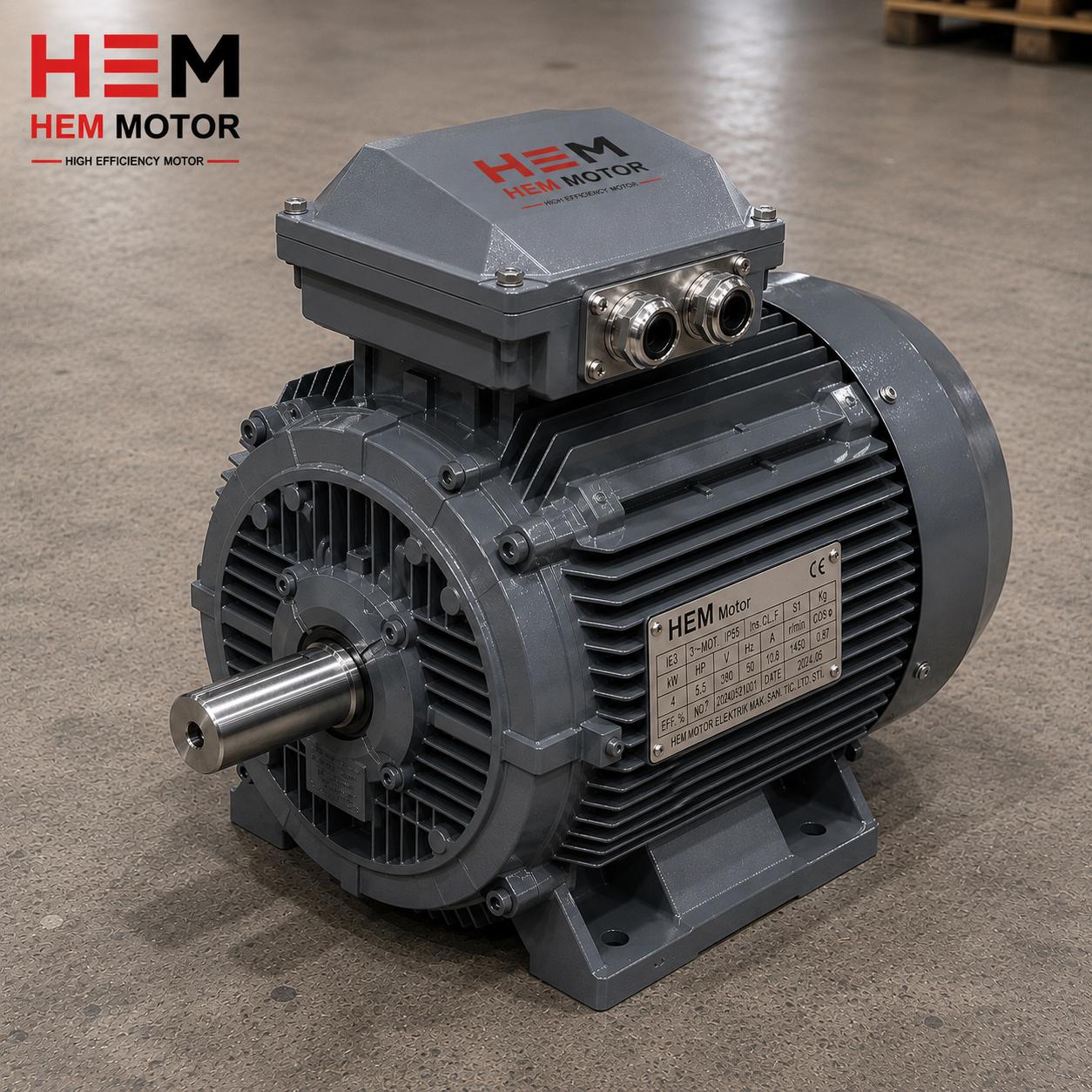
The IE5 synchronous reluctance motor (SynRM) has become a focal point in industrial drive efficiency discussions. By eliminating rotor bars and windings, these machines remove almost all rotor losses, delivering both lower operating temperatures and higher efficiency than conventional induction motors. Yet during procurement, one question comes up again and again: "Do these motors need power factor correction, that is, capacitor-based compensation?" The concern stems from facility managers worrying about reactive energy penalties, capacitor banks and how the drive supply behaves.
As the manufacturer and supplier delivering IE5 SynRM motors from stock, we believe this topic must be clearly understood for correct system design. In this article we examine the power factor behavior of the synchronous reluctance motor, the effect of variable frequency drive (VFD) supply on reactive energy, and whether compensation is genuinely necessary, all on a solid technical basis.
How the Synchronous Reluctance Motor Works and Its Power Factor Character
A synchronous reluctance motor produces torque through differences in magnetic permeability (reluctance) within its rotor. There are no magnets and no windings in the rotor; instead, sequential flux barriers and flux paths are stamped into the laminations. This structure makes direct-on-line operation impossible. In other words, the IE5 synchronous reluctance motor always operates together with a variable frequency drive.
At this point, power factor must be considered on two distinct planes. The first is the power factor at the motor terminals; the second is the power factor of the exchange between the facility and the grid. The power factor at the motor terminals of a synchronous reluctance motor is usually somewhat lower than that of a conventional induction motor. This is because the motor has no magnets and must draw magnetizing (reactive) current from the drive to establish its magnetic field.
A typical terminal power factor may fall between 0.65 and 0.80. At first glance this looks low and tempts engineers to add a capacitor bank. But here a crucial technical fact must be stressed: the power factor at the motor terminals is not the same thing as the power factor measured at the facility's utility meter.
How the Drive Supply Affects Reactive Energy
This is the heart of the matter. The IE5 synchronous reluctance motor is never connected directly to the grid; a frequency converter sits in between. The input side of this drive has a rectifier bridge. In a standard diode-bridge drive, the displacement power factor on the input side is between 0.95 and 0.98, that is, close to unity.
The implication is significant: no matter how low the cosφ at the motor terminals, that reactive power is supplied by the capacitors on the drive's DC bus. The magnetizing current the motor requires is provided not by the grid but by the drive's own DC link capacitance. Consequently, on the grid side, at the point measured by the reactive energy meter, the motor's low power factor is invisible.
Displacement Power Factor Versus Total Power Factor
There is a subtlety here. Although the displacement power factor of drives is high, diode-bridge rectifiers draw distorted, harmonic-rich current from the grid. These harmonics reduce the total (true) power factor. So when it comes to reactive energy penalties, the real issue is not classical inductive compensation but harmonic current management.
- Displacement power factor: Naturally high in diode-bridge drives; requires no additional compensation.
- Distortion factor: Caused by harmonics; cannot be corrected with classical capacitors, which may even resonate with harmonics.
- Total power factor: The product of the two, and the value the meter sees.
For these reasons, the answer to "does the IE5 SynRM motor need classical compensation?" is, in most applications, no. The low cosφ at the motor terminals does not reflect onto the grid because the drive acts as a buffer.
Correct Assessment of Reactive Energy Penalties
In the tariff structures of many countries, a penalty applies when the ratio of reactive energy drawn to active energy exceeds a certain threshold (often 20 percent inductive, 15 percent capacitive). If a facility has IE5 synchronous reluctance motors fed by drives, the inductive reactive energy those motors draw from the grid is quite low, because the magnetizing load is isolated by the drive.
However, one scenario deserves attention: if the facility still has conventional induction motors, transformers or idling equipment connected directly to the grid, these draw inductive reactive power. In that case the need for compensation arises not from the SynRM motors but from the rest of the facility. The compensation decision must therefore be made by looking at the reactive energy balance of the entire facility, not a single motor.
The Risk of Capacitive Over-Correction
An important warning: if the facility has an old fixed capacitor bank and you replace classical induction motors with drive-fed IE5 motors, the inductive load drops but the capacitor bank stays the same. The facility then shifts to the capacitive side and incurs a capacitive reactive penalty. This is a common, easily overlooked error in modernization projects. For this reason, the existing compensation panel must be re-sized during motor renewal projects.
Harmonic Management and Correct Drive Selection
With IE5 synchronous reluctance motors, the real engineering effort is directed toward harmonic control rather than classical compensation. The main methods for managing harmonics include:
- AC line reactor: A simple, economical solution added at the drive input; significantly reduces current harmonics.
- DC link choke: Built into many modern drives, it lowers THD.
- Passive harmonic filters: Target specific harmonic orders.
- Active Front End (AFE) drives: Keep harmonics very low, bring the power factor close to unity, and can regenerate energy back to the grid.
Depending on facility size and total installed drive power, the right solution varies. A line reactor suffices for a single low-power motor, while an active harmonic filter or AFE drives are preferred in facilities with many drives. We evaluate this selection together with you during design.
Recommendations for Correct Motor and Drive Supply
As the manufacturer and supplier, we recommend treating not just the motor but the motor-drive-filter package as a whole when selecting an IE5 SynRM motor. For motors operating in cold climates, low-temperature and winter-rated motor options should be evaluated separately; our content on IE4 motor cold-climate performance offers useful guidance.
Selecting efficient motors at the correct power is just as important as compensation. An oversized motor lowers both its efficiency and power factor at part load. We recommend our guide on oversizing and right-downsizing in efficient motors. In pump and fan applications, motor life can be significantly extended with surge protection.
So that we can deliver the most suitable IE5 synchronous reluctance motor from stock, simply share your application load, operating speed and grid conditions with us. Our technical team will size the motor and harmonic management solution together and provide a fast quote. For more, visit our homepage.
The Reactive Behavior Difference Between Induction Motors and IE5 SynRM
Understanding the classical induction motor makes it easier to grasp the behavior of the synchronous reluctance motor. A direct-on-line induction motor continuously draws inductive reactive power from the grid to establish its magnetic field. This reactive power is largely constant regardless of load and appears directly on the reactive energy meter. That is exactly why capacitor banks were mandatory in classical facilities; the inductive reactive power drawn by the motors had to be generated locally to reduce grid burden and penalties.
With the IE5 synchronous reluctance motor, the situation is fundamentally different. The motor is connected not to the grid but to the drive. The capacitors on the drive's DC bus exchange the magnetizing energy the motor needs, like a buffer, every cycle. The grid, meanwhile, supplies only active power and the drive's rectifier losses. This architecture completely isolates the motor's reactive load from the grid. As a result, an IE5 SynRM doing the same job draws far less inductive reactive power on the grid side than a classical induction motor, improving your facility's power factor balance.
The Importance of Phased Transition in Modernization
Converting a facility entirely to IE5 SynRM motors is usually a phased process. During this transition, the facility's reactive balance changes continuously. While some motors still draw inductive reactive power from the grid as induction machines, the new drive-fed motors eliminate that load. In this dynamic environment, a fixed (non-stepped) capacitor bank is dangerous, because as the inductive load decreases the system may shift to the capacitive side. For this reason, modern facilities prefer automatic, microprocessor-controlled stepped compensation panels that switch capacitor stages in and out according to the instantaneous reactive state.
Efficiency, Sustainability and Total Cost of Ownership
Power factor alone should not drive IE5 synchronous reluctance motor selection. The real return of these motors is the energy saving they provide thanks to their high efficiency class. The absence of conductor losses in the rotor allows the motor to run at a lower temperature, which extends bearing and insulation life. Lower operating temperature reduces cooling needs and failure probability. From a total cost of ownership (TCO) perspective, the purchase price of the motor is small compared with the energy it consumes over its lifetime.
In continuous, long-duration applications, the saving from the IE5 efficiency class pays back the investment difference within a few years. Motor selection should therefore be based not only on the label price but on the lifetime energy cost. The power factor concern is just a small piece of this bigger picture and, as we have seen, is in most cases managed automatically thanks to the drive architecture.
Information to Gather for Correct Design
So that we can offer you the most suitable solution, we recommend gathering the following: the type of load the application drives (pump, fan, compressor, conveyor), rated power and speed, daily operating hours, grid short-circuit power, the structure of the existing compensation panel, and the total power of other drive-fed loads. With this information, we size both the correct motor and, if needed, the harmonic management solution in one pass, helping you avoid surprise reactive or harmonic penalties.
Frequently Asked Questions
Should I connect a capacitor bank to my IE5 synchronous reluctance motor?
No, capacitors are not connected directly to the motor terminals. Because the motor is fed through a drive, its magnetizing (reactive) needs are met by the capacitors on the drive's DC bus. If you wish to add capacitors on the grid side, that decision must be based on the reactive energy balance of the entire facility; otherwise there is a risk of capacitive over-correction.
Does the motor's low power factor cause a reactive energy penalty?
Generally no. The low cosφ at the motor terminals is isolated by the drive's rectifier structure and does not appear at the grid meter. The drive's displacement power factor is already close to unity. The penalty risk comes mainly from harmonic currents, which are managed with a line reactor or harmonic filter.
What happens if I replace my existing induction motors with IE5 SynRM?
Your inductive reactive load decreases, which is positive. However, if your facility has a fixed capacitor bank, the system may shift to the capacitive side and you could incur a capacitive penalty. Therefore, during motor renewal, your existing compensation panel must be re-sized and preferably switched to automatic (stepped) compensation.


