 English
 Türkçe
Summary (TL;DR)
- An IE5 synchronous reluctance motor (SynRM) cannot start direct-on-line; it always requires a variable frequency drive (VFD). Motor and drive must therefore be selected together as a matched package.
- Sensorless vector control (encoderless) removes encoder cost and wiring complexity, but low-speed rotor position estimation is the key engineering challenge.
- At medium and high speed, back-EMF based observers are sufficient; at zero and low speed, high-frequency signal injection (HF injection) is required.
- For high-dynamic, full-torque-at-zero-speed, or precise positioning applications an encoder may still be the right choice; the decision depends on the application.
- HEM Motor manufactures and supplies the IE5 motor and a matched drive as a single package, delivered with autotune and commissioning support.
As energy-efficiency regulations tighten, industrial plants are migrating from classic induction motors to the IE4 and IE5 motor classes. One of the strongest candidates in this transition is synchronous reluctance motor (SynRM) technology. SynRM delivers high efficiency without permanent magnets, which means a stable supply chain independent of raw-material price swings and a low failure risk. However, this topology has a critical property: a synchronous reluctance motor cannot be connected directly to the grid (line-start). It must always be driven by a VFD. In this article we explain in detail how sensorless vector control (encoderless) works, the challenges of low-speed rotor position estimation, and how to choose the correct drive package. To review the matched motor and drive family, visit our electric motor prices page.
Why Does a Synchronous Reluctance Motor Need a Drive?
Induction (squirrel-cage) motors can start on their own when connected directly to the grid, thanks to currents induced in the rotor. A synchronous reluctance motor works on a completely different principle. Its rotor has no windings, no cage, and no permanent magnets; it is only an anisotropic (directional) lamination stack with flux barriers that force the magnetic flux along preferred paths. The rotor locks onto the stator's rotating magnetic field and turns at synchronous speed.
This structure cannot produce the asynchronous starting torque needed for direct-on-line start. When energized at a fixed 50 Hz, the rotating field turns far faster than the rotor inertia can capture, so the motor merely vibrates instead of turning. That is why SynRM products in the IE5 motor class always operate with a VFD. The drive starts the frequency from zero and ramps it up gradually so the rotor stays synchronized with the rotating field.
This directly affects the buying decision: treating the drive as an afterthought when purchasing an IE5 motor is a mistake. Motor and drive must be compatible at the level of flux model, parameters, and control algorithm. For this reason HEM Motor manufactures and supplies the motor and drive as a single matched package, which shortens commissioning and avoids performance loss caused by mismatch. See IE5 Synchronous Reluctance Drive Parameterization for detailed commissioning steps.
How Does Sensorless (Encoderless) Vector Control Work?
Vector control (field-oriented control, FOC) splits the stator current into two components: a flux-producing component (d-axis) and a torque-producing component (q-axis). For this decomposition to be correct, the drive must know the rotor's angular position (electrical angle) at every instant. In the classic solution this information comes from an encoder or resolver mounted on the shaft end.
Sensorless vector control instead estimates the rotor position through a mathematical model rather than a physical sensor. Using the measured stator voltages and currents, the drive runs an observer algorithm and computes the rotor's position and speed in real time. The advantages are clear:
- Encoder and resolver cost is eliminated.
- The encoder cable, connectors, and their susceptibility to electromagnetic noise disappear.
- A mechanical failure point is removed; the encoder is one of the components that fails most often in vibrating, dusty environments.
- The shaft end is freed up; total length is shortened.
These advantages make sensorless vector control the first choice in pumps, fans, compressors, conveyors, and many general-purpose drive applications. But the whole story lies in the low-speed region.
Low-Speed Position Estimation: The Crux of the Matter
There are two main method families for rotor position estimation, each working in a different speed range.
Back-EMF Based Observers
When the motor turns, the rotor's anisotropy and flux induce a back electromotive force (back-EMF) in the stator. The amplitude and phase of this signal carry information about rotor position. The drive extracts the position from this signal using techniques such as a voltage model or an extended observer (Extended EMF, sliding-mode observer, Luenberger observer). This method works excellently at medium and high speed.
The problem: back-EMF amplitude is proportional to speed. As speed drops, the signal weakens; at zero speed the back-EMF is zero too. Therefore this method cannot perform reliable position estimation below roughly 5-10% of rated speed, and is completely blind at zero speed.
High-Frequency Signal Injection (HF Injection)
To find rotor position in the low-speed and zero-speed region, the motor must be excited with an additional high-frequency signal beyond the fundamental. A synchronous reluctance motor offers a special advantage here: the rotor's magnetic anisotropy (the difference between d-axis and q-axis inductances — the saliency ratio) is very pronounced. The drive injects a high-frequency voltage signal into the stator and measures the resulting current response. Because of the anisotropy, the current response varies with rotor position, and the drive derives the rotor angle from this difference.
The HF injection method can find the rotor position even when the motor is not turning at all (zero speed) and at very low speeds. This makes demanding scenarios possible, such as starting from zero speed at full load and holding a suspended load. In practice, a good drive uses HF injection at low speed and a back-EMF observer at high speed, with a smooth transition (blending) between the two.
Zero Speed, Cogging, and Pole-Ambiguity Challenges
Sensorless control has several classic challenges, and correct drive selection manages them.
- Polarity ambiguity: HF injection finds position from anisotropy, but distinguishing which way the rotor is pointing (a 180-degree ambiguity) at first startup requires an additional polarity-detection pulse. A correctly parameterized drive does this automatically.
- Cogging and torque ripple: At very low speed, ripple in torque production can introduce noise into the position estimate. A quality lamination design and good current regulation suppress this.
- Magnetic saturation: Under high load the d-axis inductance saturates; anisotropy decreases and HF injection resolution can drop. The drive's flux model must account for load-dependent inductances — which is why a matched motor-drive package matters.
- Initial startup (sticking): In a static state the rotor can magnetically "stick," and the initial break-away torque requires careful management.
Our article IE5 Synchronous Reluctance Motor Starting and Static Torque examines startup scenarios in detail.
When Is an Encoder Still Needed?
Sensorless vector control is sufficient in many applications, but in some cases an encoder or resolver is still the right choice:
- Applications that must hold a load permanently at zero speed under full load (for example, a suspended load in hoisting/crane systems).
- Servo-like applications requiring very high dynamics and reacting to sudden torque changes within milliseconds.
- Machines requiring precise positioning (position control).
- Continuous, stable operation at extremely low speed (for example, around a thousandth of rated speed).
For the vast majority of continuous-load, speed-control applications such as pumps, fans, compressors, extruders, and conveyors, the sensorless solution is superior both technically and economically. We make the right decision together based on your application profile.
Autotune, Parameterization, and the Flux Model
The heart of sensorless control is an accurate electrical model of the motor. The main parameters the drive must know are: stator resistance, d-axis and q-axis inductances (and how they vary with load/saturation), pole count, and inertia. Modern drives can measure these parameters via automatic parameter identification (autotune) by briefly exciting the motor.
However, autotune for a synchronous reluctance motor is more delicate than for an induction motor, because the inductances change strongly with load, and accurate tabulation of these curves determines position estimation accuracy. HEM Motor pre-loads the drive with factory parameters for every IE5 motor it produces; only fine tuning is needed on site. This reduces commissioning from days to hours. For a comparison of control modes, the article Scalar (V/f) and Vector Control in Induction Motors is a useful reference.
Choosing the Correct Drive (VFD) Package
Points to watch when selecting a SynRM drive:
- SynRM support: The drive must support synchronous reluctance motor control mode (not induction-only or PM-only).
- Low-speed sensorless performance: The drive's HF injection capability and transition algorithm must meet your target minimum speed.
- Current and overload capacity: Sizing according to starting torque.
- Matching: A parameter set suited to the motor's flux model.
- Protection class and environment: Enclosure and cooling appropriate to the field environment.
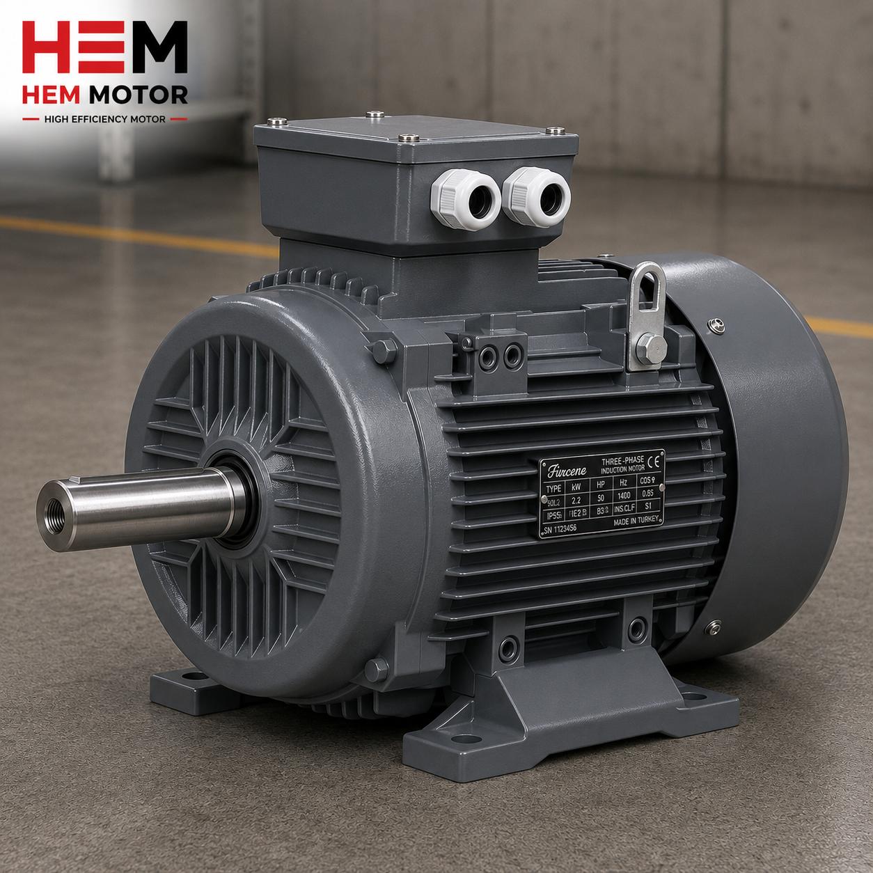
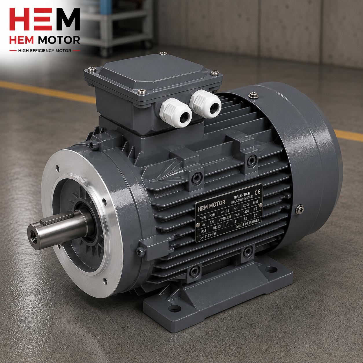
The HEM Motor product family covers IE3, IE4, and IE5 efficiency classes; it offers power up to 355 kW, B3/B5/B35 mounting options, a cast iron frame, IP55 protection, and class F insulation. Because we deliver the motor and drive as a single package, supply, stock, and quotation processes run from one source, with spare parts and technical support backed by the manufacturer. Explore our High-Efficiency Electric Motors product page and our IE5 Electric Motors category.
Purchasing Checklist
- What is the application's minimum and maximum speed range? Will a load be held at zero speed?
- Is the sensorless solution sufficient, or is an encoder required?
- What are the starting torque and overload profile?
- Are the motor power, mounting type (B3/B5/B35), protection class, and efficiency class (IE5) suitable?
- Is the drive pre-parameterized for the motor's flux model?
By completing this list together, we clarify the correct IE5 motor and drive package, share stock and delivery time, and prepare your quotation.
Frequently Asked Questions
Can an IE5 synchronous reluctance motor run without an encoder?
Yes. In many applications a synchronous reluctance motor runs successfully with sensorless (encoderless) vector control. High-frequency signal injection is used at low speed and a back-EMF observer at high speed. An encoder is recommended only in special applications requiring permanent zero-speed operation under full load or very high dynamics.
Why can't a synchronous reluctance motor be connected directly to the grid?
Because its rotor has no cage or windings to produce asynchronous starting torque. At fixed-frequency grid voltage the rotating field turns at a speed the rotor cannot capture, so the motor cannot start. That is why SynRM products in the IE5 motor class are always driven by a VFD.
Should I buy the motor and drive separately?
Our recommendation is to buy the motor and drive as a single matched package. The accuracy of sensorless control depends on the drive being correctly parameterized to the motor's flux model (d/q inductances, saturation curves). HEM Motor supplies its manufactured motor together with a compatible, pre-parameterized drive, which shortens commissioning.


