 English
 Türkçe
The days when a motor only consumed energy are over. While a crane lowers its load, a centrifuge decelerates, or an inclined conveyor carries material downhill, the motor actually turns into a generator and converts mechanical energy back into electricity. The question is whether this energy will be wasted as heat in a brake resistor, or recovered through a common DC bus or an active front end. The IE5 synchronous reluctance motor, with its magnet-free rotor, low rotor losses and superior part-load efficiency, is an outstanding platform for this recovery; however, it cannot be connected to the grid on its own and must always be driven by a VFD (frequency converter). In this article we cover the logic of regenerative braking, four-quadrant operation, common DC bus and active front end architectures, and which solution pays for itself in which application.
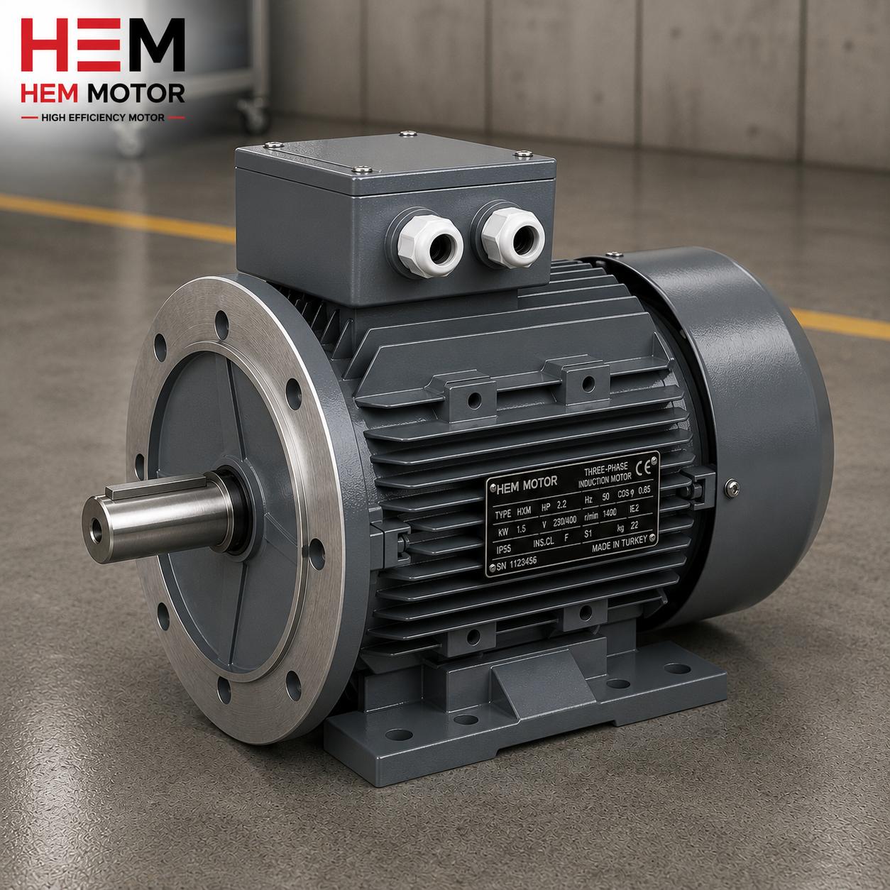
Why Is the IE5 Synchronous Reluctance Motor Suited to Regeneration?
The synchronous reluctance (SynRM) rotor contains no permanent magnets; torque arises from the difference in magnetic permeability (reluctance) in the rotor. Because there are no copper or magnet losses in the rotor, this structure delivers very high efficiency, especially at part load. When the motor switches to generator mode during braking, the low rotor loss means a larger share of the mechanical energy is converted to electricity and can be recovered. The IE5 efficiency class represents the highest "ultra premium" efficiency level currently available.
There is a critical point here: a SynRM motor cannot be run by connecting it directly to the grid. Due to its synchronous structure it always requires a drive. This requirement actually turns into an advantage, because the drive that is already present provides the infrastructure needed for four-quadrant operation and energy recovery. To review IE5 SynRM technology in general terms, see our IE5 ultra premium motor complete guide.
What Is Four-Quadrant Operation?
Consider a drive's operating state on a torque-versus-speed plane. Four-quadrant operation means the motor can run in both directions of rotation as both a motor (drawing energy) and a generator (producing energy). The four quadrants are summarized as follows:
- Quadrant 1: Forward direction, motoring — the load accelerates, the motor draws energy.
- Quadrant 2: Forward direction, generating — the load is decelerated, the motor produces energy (regenerative braking).
- Quadrant 3: Reverse direction, motoring.
- Quadrant 4: Reverse direction, generating.
The key to energy recovery lies in quadrants 2 and 4. Where the energy released in these quadrants goes determines the drive architecture. A standard drive cannot store braking energy in the DC bus capacitor; to prevent the voltage from rising, it needs either a brake resistor or a regenerative feedback path.
Where Does Braking Energy Go? Three Architectures
1. Brake Resistor
The simplest solution is to limit the rise of DC bus voltage during braking using a chopper connected to a brake resistor. The released energy is converted to heat in the resistor and dumped. This method is sufficient and economical for intermittent, short-duration and low-power braking. Its drawbacks are that all recoverable energy is lost and that it requires heat management inside the panel.
2. Common DC Bus
In an architecture where the DC buses of several drives are tied together, the energy produced by one motor during braking can be transferred directly to neighboring drives connected to the same bus that are operating in motor mode at that moment. In other words, the energy one axis produces while braking is consumed by another axis. The common DC bus is highly efficient, especially in multi-axis machines and loads that continuously balance each other, because energy circulates within the plant instead of being burned off in a resistor.
3. Active Front End
An active front end replaces the diode bridge on the grid side of the drive with a controlled, bidirectional converter. This allows braking energy to be returned to the grid even when there is no neighboring load on the common DC bus to consume it. An active front end additionally offers grid-quality advantages such as low harmonics and corrected power factor. In plants that brake continuously or at high power, this architecture provides the highest recovery. To deepen the topic of grid quality and harmonics, our article on efficient motor VFD harmonic filter and line will be useful.
Which Solution for Which Application?
The right solution depends on the application's braking profile. A general roadmap:
- Cranes and hoisting: Continuous generator mode during load lowering; common DC bus or active front end yields serious savings.
- Centrifuges and test benches: High inertia and frequent stops; recoverable energy is large.
- Winders and tensioning: One axis tensions, another brakes; ideal for a common DC bus.
- Inclined/downhill conveyor: The motor is continuously a generator as material descends; an active front end pays back quickly.
- Intermittent short braking: For low power and infrequent stops, a brake resistor is sufficient and economical.
When deciding, annual braking hours, braking power and unit energy cost should be evaluated together. In a plant that brakes continuously at high power, an active front end or common DC bus usually repays the extra investment in a short time. For general regenerative braking principles, our article on regenerative braking in electric motors is a basic reference.
Motor and Drive Compatibility: The Single-Package Advantage
Because IE5 SynRM motors cannot run without a drive, selecting the motor and drive to be compatible from the start is the foundation of performance. A mismatched motor-drive pair cannot deliver the declared IE5 efficiency in the field; regenerative capacity cannot be used and commissioning drags on. Points to watch in correct matching:
- Drive type: A drive that supports the SynRM control algorithm and can operate in four quadrants.
- Regenerative capability: The brake resistor, common DC bus or active front end option suited to the application.
- Power and torque matching: Verification of rated torque and overload capacity against the load.
- Lead time and stock: Supply aligned with the commissioning schedule.
As a manufacturer and seller, HEM Motor matches the motor and drive as a single package, with stock, quotation and lead-time assurance, so IE5 motor and drive compatibility is guaranteed from the start. You can reach all our IE5 and drive solutions through the HEM Motor homepage.
Application Examples: Where Does the Energy Return?
To see the concrete benefit of regenerative braking, let us look closely at typical applications. Each application has a different braking profile, and this profile determines the most suitable architecture.
Cranes and Hoisting Systems
While a crane lifts a load the motor draws energy; while lowering the load gravity tries to accelerate it and the motor brakes, switching to generator mode. Energy is released continuously throughout load lowering. When this energy is burned off in a brake resistor it is both wasted and heats the panel; when recovered through a common DC bus or active front end, every lowering cycle turns into a saving. Because braking is frequent and predictable in crane applications, the recovery investment usually pays back quickly.
Centrifuges and Test Benches
High-inertia centrifuges store large amounts of energy when accelerated; this kinetic energy is released again when stopped. In centrifuges that stop and start frequently this cycle repeats many times, so the total recoverable energy is large. On test benches, the unit under test often behaves like a generator; returning the produced energy to the grid or transferring it to neighboring loads significantly reduces the energy cost of the test system.
Winders and Inclined Conveyors
In winder applications one axis tensions the material while another brakes; these two axes can share energy directly over a common DC bus. On inclined or downhill conveyors, the motor is in generator mode almost continuously as material descends; here the energy released is continuous and an active front end investment pays back very quickly. These applications are the areas where four-quadrant operation and energy recovery provide the most visible benefit.
The Economic Logic of Energy Recovery
The value of a regenerative braking investment is hidden in the monetary worth of the energy released during braking. When this energy is converted to heat in a brake resistor it is entirely lost; moreover, an extra cooling load arises to remove the released heat from the panel. When recovered through a common DC bus or an active front end, this energy is reused within the plant or sold back to the grid. The main variables that determine the investment decision are:
- Annual braking hours: How long per year does the motor run in generator mode? The longer the time, the greater the return on recovery.
- Braking power: If the power released at each braking is high, the energy recovered is also high.
- Unit energy cost: As the cost of electricity rises, recovery pays back faster.
- Reduced cooling load: When the brake resistor is removed, panel heat drops, which is an additional indirect gain.
When these variables are evaluated together, in a plant that brakes continuously at high power an active front end or common DC bus architecture usually repays the extra investment in a short time. By contrast, for infrequent, low-power braking a brake resistor is still the most sensible choice.
Commissioning and Engineering Considerations
When building a regenerative system, a few engineering points must be addressed from the start. First, in a common DC bus architecture the voltage levels and protection coordination of the drives connected to the bus must be compatible; otherwise a fault in one drive can spread across the whole bus. Second, when an active front end is used, the quality of the energy returned to the grid must be evaluated in terms of harmonic limits and power factor. Third, the chopper, brake resistor or regenerative path must be correctly sized so that the DC bus voltage stays within a safe limit at the moment of braking.
The common denominator of all these decisions is treating the motor and drive as a compatible whole. Considering the SynRM motor separately from the drive produces an incomplete solution in terms of both efficiency and regenerative capacity. For this reason, treating the motor, drive and braking architecture as a single engineering decision guarantees the expected performance in the field. To review the basic principles of IE5 technology, our IE5 ultra premium motor complete guide is a guide.
Frequently Asked Questions
Can an IE5 synchronous reluctance motor be connected directly to the grid?
No. Due to its synchronous structure the SynRM motor must always be driven by a VFD (frequency converter); it cannot start with a direct grid connection. This requirement turns into an advantage for regeneration, because the drive that is already present provides the infrastructure needed for four-quadrant operation and energy recovery.
What is the difference between a common DC bus and an active front end?
A common DC bus transfers braking energy to neighboring drives connected to the same bus; that is, the energy is consumed by another load within the plant. An active front end returns the energy to the grid, enabling recovery even when there is no neighboring load to consume it; it also provides low harmonics and corrected power factor. A common DC bus stands out in multi-axis machines, while an active front end stands out for a single large load.
When is a brake resistor sufficient?
For intermittent, short-duration and low-power braking, a brake resistor is both sufficient and economical. Because the released energy is small and infrequent, the return on recovery may not justify the investment. By contrast, in plants that brake continuously or at high power, a common DC bus or active front end pays for itself quickly.


