English
 Türkçe
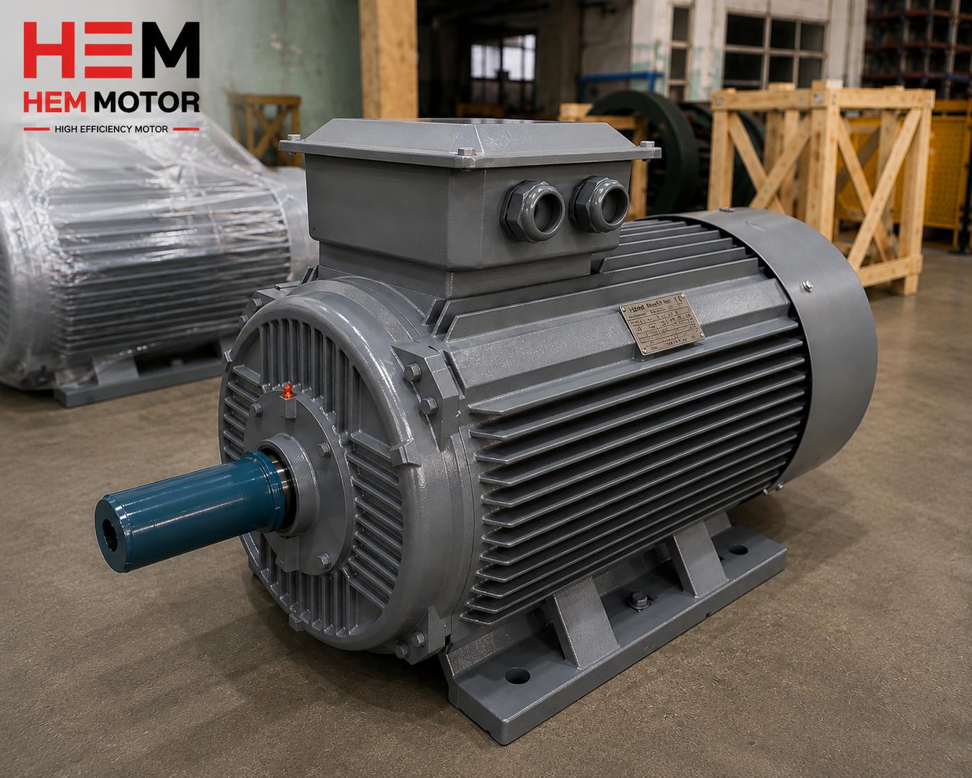
When you purchase a high-efficiency IE4 Super Premium electric motor, one of the most critical factors determining its service life is how the winding temperature is monitored and how the motor is protected against overheating. The overwhelming majority of electric motor failures originate from thermal fatigue of the insulation system, in other words from the windings exceeding their permitted temperature limit. This is exactly where PTC thermistors (DIN 44081 / DIN 44082) embedded inside the stator windings provide the most reliable layer of protection, warning the motor against dangerous overheating within seconds. At HEM Motor, our IE3 Premium and IE4 motors can be supplied with thermistor outputs already fitted at the ordering stage, so that on critical drives in your facility the winding protects itself by directly measuring its own internal temperature. In this guide we explain the operating principle of the PTC thermistor, the classification in the DIN standards, how it differs from PT100 RTDs and bimetal protectors, and what to specify for correct supply when ordering your motor.
What Is a PTC Thermistor and How Does It Work in an IE4 Motor?
PTC stands for "Positive Temperature Coefficient." A PTC thermistor is a semiconductor temperature sensor that exhibits a low and nearly constant resistance up to a defined threshold temperature, and then increases its resistance abruptly and very steeply once that threshold (the nominal response temperature) is exceeded. This sharp change in resistance is easily detected by a thermistor protection relay, which de-energizes the contactor feeding the motor and stops it.
In IE4 motors, the thermistors are embedded directly into the stator winding overhangs (winding ends) during manufacturing. Typically, in a three-phase motor, one thermistor is placed in the hottest region of each phase winding, and the three thermistors are connected in series and brought out to separate leads in the terminal box. Because the sensor sits directly inside the copper winding, at the very point where heat is generated, it measures the winding temperature truly and without delay. Whereas thermal relays that measure line current only make an indirect estimate of heating, the embedded thermistor monitors the source directly.

The 100% copper windings and class F insulation material (class H on request) of HEM Motor's IE4 range, combined with thermistor protection, offer a thermally very safe operating window. The superior heat conduction of the copper winding ensures the thermistor accurately represents the true winding temperature.
DIN 44081 and DIN 44082 Standards: Single and Triplet Thermistor Sets
Winding protection thermistors are manufactured to the internationally accepted DIN 44081 and DIN 44082 standards (equivalent to IEC 60034-11). These two standards clearly define the resistance-temperature characteristic of the thermistor and its nominal response temperatures (NAT - Nominal Response Temperature).
- DIN 44081: Defines the resistance-temperature curve and test conditions of a single thermistor element (single sensor). A single sensor is generally used for laboratory measurement or single-point monitoring.
- DIN 44082: Defines the characteristic for a set of three thermistors connected in series (a triplet). This is the standard used in three-phase motors with one thermistor per phase, and it is the most common in industrial motor protection.
In both standards, the nominal response temperature of the thermistor is selected according to the insulation class of the motor. For a class F IE4 motor, the permitted winding temperature limit is around 155 °C; therefore the protection thermistor is selected with a response temperature class that stays below this limit and stops the motor before the insulation is damaged. With class H insulation the limit is higher, so the thermistor is chosen with a correspondingly higher response temperature. The standard provides these temperatures in defined steps from 60 °C up to 180 °C.
The Difference Between a PTC Thermistor, PT100 and Bimetal Protector
Distinguishing the three basic sensor types used for winding temperature protection is important for placing a correct motor order. You may also want to review our in-depth guide, Motor Winding Temperature Monitoring: PT100 and PTC Thermistor.
PTC Thermistor: Threshold Protection (On/Off Logic)
The PTC thermistor is a threshold sensor. It does not display a continuous temperature value; it only provides the information "limit exceeded / not exceeded." Its advantage is that it is extremely fast, inexpensive and reliable. When used together with a thermistor protection relay, the motor is stopped the instant the threshold temperature is reached. It is the ideal solution when a simple and robust trip protection is required on critical drives.
PT100 RTD: Continuous Temperature Measurement
The PT100 is a resistance temperature detector (RTD); the resistance of the platinum element varies linearly in proportion to temperature. The PT100 gives you the actual temperature value (°C) continuously. This allows you to track the temperature trend, set alarm and trip thresholds separately, and perform predictive maintenance. It is generally preferred on large-power motors, in critical processes and wherever continuous monitoring is desired. It is more costly and requires a transmitter/reader.
Bimetal / Thermal-Click Protector
The bimetal (thermal-click) protector is a simple device made of two metals that change shape with temperature and open a mechanical contact at the threshold temperature. It can be wired directly in series with the contactor coil circuit, with no additional relay required. However, it responds more slowly than a PTC thermistor, is subject to mechanical wear, and offers more limited response-temperature steps.
In summary: if you want continuous value reading and predictive maintenance, the PT100 is the right choice; if you want fast and reliable threshold trip protection, the PTC thermistor is the most suitable. In many critical applications both are ordered together.
Which Fault Scenarios Does the PTC Thermistor Protect Against?
The classic thermal overload relay, which measures line current, is only triggered by a rise in current. Yet the motor winding can overheat even while the current appears normal. The embedded thermistor steps in during these "hidden" heating scenarios:
- Overload: An increase in mechanical load raises the current and therefore the winding temperature; the thermistor stops the motor once the threshold is reached.
- Blocked rotor (locked shaft): When the shaft cannot turn, the windings overheat within seconds; the embedded sensor responds rapidly.
- High ambient temperature: Above 40 °C ambient, the winding can exceed its permitted limit even though the current is normal. A current-measuring relay does not see this, but the thermistor does.
- Cooling failure: A blocked fan cowl, dirty fins or a stopped fan impair the motor's heat dissipation. The thermistor directly detects the heating caused in the winding by inadequate cooling.
- Low-speed operation with a variable frequency drive (VFD): When a self-cooled motor runs slowly at low frequency, its fan cannot generate enough air; the motor heats up even though the current is at rated value. This is the scenario where the embedded thermistor is most critical in VFD applications.
- Single phasing (phase loss): Loss of one of the three phases causes unbalanced heating in the remaining phases; the thermistor placed in each phase catches this.
- Frequent starting: Heat accumulated from frequent starting of high-inertia loads is monitored by the thermistor.
The Thermistor Protection Relay (Tripping Device) and Wiring
An embedded PTC thermistor does not provide protection on its own; it must always work with a thermistor protection relay (tripping device). This relay continuously monitors the resistance of the thermistor. When the resistance exceeds the threshold value corresponding to the response temperature (typically around 3 kΩ), the relay changes its output contact and de-energizes the main contactor. Thermistor relays also detect a short circuit or open circuit in the thermistor line, flagging a defective sensor; this further improves safety.
The thermistor connection in the terminal box follows these principles:
- The thermistor leads are brought out as two small-section control leads (usually marked T1-T2), separate from the motor power terminals.
- These leads are connected to the thermistor input terminals of the thermistor protection relay.
- Mains voltage must never be applied to the thermistor circuit; this is a small-signal measurement circuit.
- The relay output contact is wired in series with the contactor coil or into the stop/fault input of the VFD.
Thanks to this arrangement, the motor is stopped safely the instant the winding reaches its critical temperature, without waiting for a rise in current.
Ordering the Motor with Thermistor Outputs: Correct Supply
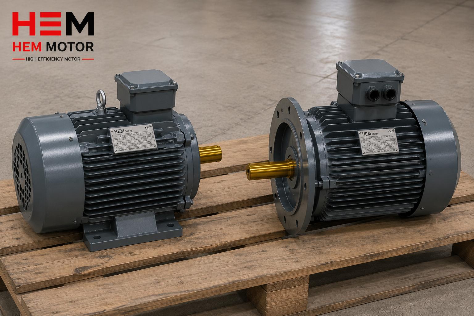
The thermistor embedded in the winding is a component that must be placed while the motor is being wound; for this reason it is not practical to add it in the field afterwards. The correct approach is to order the motor with thermistor outputs (with PTC) from the outset. At HEM Motor we can manufacture our IE3 Premium and IE4 electric motors in the 0.55 kW – 355 kW power range, equipped with a triplet PTC thermistor set in accordance with the DIN 44082 standard, in line with your request.
The critical information to specify when ordering is:
- Motor insulation class (F standard, H option) and the corresponding thermistor response temperature class.
- Thermistor type: PTC (threshold), or PT100 for continuous monitoring, or both.
- Whether the motor will operate with a variable frequency drive — for VFD low-speed applications, the embedded thermistor is our strong recommendation.
- Whether an additional connection arrangement or a separate box is needed in the terminal box for the thermistor leads.
Thanks to the low losses of the IE4 Super Premium efficiency class, the motors already run cooler; however, on critical processes, winding temperature protection safeguards your investment independently of efficiency. By reviewing our broad product range and the information on electric motor prices, you can identify the most suitable protected motor for your application.
The Combined Value of IE4 Efficiency and Thermal Safety
IE4 class motors run cooler at the same load thanks to lower energy losses, which extends insulation life. Nevertheless, no efficiency class on its own provides protection against abnormal conditions such as a blocked rotor, cooling failure or overload. In our IE4 high-efficiency electric motors family, offered with 100% copper windings, F/H insulation and IP55 (IP65/66 on request) enclosure protection, the embedded thermistor option makes your motor both energy-efficient and thermally safe. For the correct selection of protection devices, our article on electric motor protection and thermal relay selection serves as a useful additional resource, and you can explore the full category in our IE4 electric motors guide.
Frequently Asked Questions
Are a PTC thermistor and a thermal relay the same thing?
No. A thermal relay measures the current flowing through the motor power line and is triggered when the current rises; it estimates the winding temperature indirectly. A PTC thermistor, on the other hand, is embedded inside the winding and measures the temperature directly at its source. In situations where the current appears normal — such as high ambient temperature, cooling failure or low-speed operation with a VFD — only the embedded thermistor provides protection. In an ideal application both are used together: the thermal relay against overcurrent and the thermistor against overtemperature.
What is the difference between DIN 44081 and DIN 44082?
DIN 44081 defines the resistance-temperature characteristic of a single thermistor element, while DIN 44082 defines the characteristic for a set of three thermistors connected in series (a triplet). In three-phase motors, DIN 44082 is used with one thermistor per phase, and it is the most common standard in industrial winding protection. In both standards, the nominal response temperature of the thermistor is selected according to the motor's insulation class (F or H).
Why is a thermistor important on an IE4 motor running with a variable frequency drive?
A self-cooled (TEFC) motor has its cooling fan mounted on the shaft, so it turns slowly at low speed and cannot generate enough cooling air. While running at low frequency with a VFD, the motor can overheat even though the current is at rated value. A current-measuring thermal relay cannot see this condition. A PTC thermistor embedded in the winding measures temperature directly and therefore safely protects the motor in this scenario. This is why we particularly recommend ordering motors intended for VFD operation with thermistor outputs.