English
 Türkçe

In braked motor applications, correct stopping performance often depends less on the motor itself and more on a small but critical component that powers the brake: the brake rectifier. On IE4 Super Premium efficiency motors, the spring-applied DC brake mechanism is energised through this rectifier, which converts the incoming alternating current into the direct current the brake coil needs. The rectifier type, whether half-wave or full-wave, the voltage applied to the brake coil, and therefore the stopping time, are all directly determined by this choice. From conveyor lines to cranes and hoisting systems, precise positioning and safe stopping begin with this selection.
At HEM Motor, the engineering heritage we have carried since 1979 is today channelled into IE4 class high-efficiency braked motor solutions. Across a power range from 0.55 kW to 355 kW, with 1000/1500/3000 rpm options and B3/B5/B14/B35 mounting types, choosing the correct rectifier for the brake group of our motors is a matter that cannot be overlooked for your plant's efficiency, safety and maintenance cost. In this article we detail brake rectifier compatibility, the difference between half-wave and full-wave, fast braking techniques and the correct supply strategy.
Our goal is to help you ask the right technical and operational questions when making a purchasing decision. Because an incorrectly selected rectifier can limit the stopping performance of even the highest-quality motor, while a correctly chosen one raises the tempo of your production line, improves product safety and enhances operator comfort.
How Does the Brake System Work on a Braked IE4 Motor?
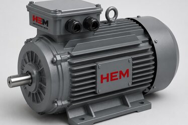
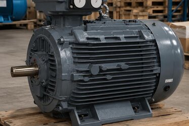
An IE4 class braked motor is equipped with a DC electromagnetic brake integrated into the rear of its frame. This brake works on the "spring-applied, electrically released" principle: when there is no power, springs press the brake disc and stop the motor; when power is supplied, the electromagnetic coil overcomes the springs and releases the brake. This structure is extremely important for safety, because the moment power is cut, the brake automatically engages and the load is held safely.
Since the brake coil runs on DC (direct current), a brake rectifier is required to convert the AC voltage from the supply into direct current. This small module is usually mounted inside the motor terminal box or in the control panel. The rectifier not only converts the voltage but, in some types, also provides additional circuit functions for rapid stopping.
The Safety Logic of the Spring-Applied Brake
The spring-applied brake is a "fail-safe" design. In situations such as power failure, emergency stop or contactor opening, the brake closes by itself. This feature is vital especially in crane, lift, hoisting and positioning applications; free-fall or uncontrolled movement of the load is prevented. The combination of the high efficiency of IE4 motors with this safe brake structure provides both energy savings and operational safety.
What Is a Brake Rectifier and Why Is It Critical?
A brake rectifier is a power electronics module that supplies direct current to the motor's brake coil. Its task is not only to convert AC to DC; it also influences the release and apply timing of the brake coil. The rectifier type determines the output voltage, and therefore the speed at which the brake is released and re-engaged.
Selecting the wrong rectifier in a plant can lead to these problems: longer stopping time, reduced positioning accuracy, premature wear of the brake disc, or overheating of the coil. For this reason, brake rectifier compatibility is a parameter that deserves as much attention as motor power during the purchasing process.
- Voltage conversion: Converts the supply AC voltage to the DC level the brake coil requires.
- Timing control: Affects how quickly the brake is released and how quickly it closes.
- Overvoltage protection: Suppresses sudden voltage spikes caused by coil inductance.
- Fast braking function: Some types cut the DC side to drastically shorten the stopping time.
The Difference Between Half-Wave and Full-Wave Rectifiers
Brake rectifiers basically come in two families: half-wave and full-wave. This distinction determines the DC voltage level obtained at the rectifier output and directly affects brake coil selection.
Half-Wave Rectifier
A half-wave rectifier passes only one half of the AC signal. As a result, the output DC voltage is approximately 45% of the supply AC voltage. For example, when supplied with 400 V AC, it produces around 180 V DC. This type easily fits inside the terminal box, is simple and economical. It is generally preferred in applications that feed the coil directly from the motor winding voltage. However, the output voltage carries more ripple and is typically used for standard stopping speeds.
Full-Wave Rectifier
A full-wave rectifier, on the other hand, uses both halves of the AC signal. The output DC voltage is approximately 90% of the supply AC voltage. When supplied with 230 V AC, it produces around 207 V DC. This makes it possible to obtain the same DC brake voltage from a lower AC supply voltage. The output is smoother with less ripple, and it is ideal when a separate supply line must be run to the brake coil. It is preferred for larger brake coils that require higher DC voltage.
An important rule is this: the rectifier type and the nominal DC voltage of the brake coil must be compatible. A wrong match produces either a weak magnetic field that cannot release the brake, or an overvoltage that burns the coil. Therefore, when sourcing a spare rectifier, it is essential to correctly identify the nameplate voltage of the existing coil and the rectifier type.
- Half-wave: Output ≈ 45% × AC supply; economical, compact, standard stopping.
- Full-wave: Output ≈ 90% × AC supply; low ripple, separate supply, high DC voltage.
- Coil nameplate voltage ↔ rectifier type match must always be checked.
- A wrong match risks brake non-engagement or coil burnout.
Fast Braking: How Do We Shorten the Stopping Time?
In a standard brake circuit, when power to the brake is cut only on the AC side, the magnetic field persists for a while due to coil inductance, and the brake closes with a delay. This delay causes an unwanted distance drift in applications requiring precise positioning. This is exactly where the fast braking technique comes into play.
In a fast braking connection, the DC output side of the rectifier is also cut by a contact. This way, the energy in the coil discharges much faster, the magnetic field collapses suddenly and the brake closes almost instantly. This method can significantly shorten the stopping time, often to one third. This technique provides critical benefits when products are stopped at a precise point on conveyor lines, and when the inertial drift of the load is prevented in crane and hoisting systems.

In Which Applications Is Fast Braking Necessary?
Not all applications require fast braking. However, a DC-side switching circuit is strongly recommended in the following situations:
- Packaging and assembly conveyor lines performing precise positioning.
- Crane, hoist and lifting systems where the load carries a free-fall risk.
- Indexing machines with frequent start-stop cycles.
- Lines where emergency stop performance is defined by safety standards.
How IE4 Efficiency Works Together With the Brake System
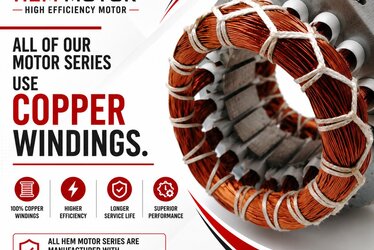
IE4 Super Premium motors generate less heat thanks to their high efficiency and reduce energy costs. In braked versions, this efficiency advantage is preserved, while the correct supply of the brake group determines the performance of the whole system. In HEM Motor's IE4 braked motor products, F-class insulation, IP55 protection and 100% copper winding are standard; this supports the stability and long life of the voltage delivered to the brake coil.
In the braked version of an efficient motor, correct rectifier selection matters not only for stopping performance but also for the energy budget. A brake coil that is supplied incorrectly continuously heats up, shortening its own life and heating the rear bearing area of the motor, negatively affecting bearing life. For this reason, the motor and the rectifier must be evaluated as a whole.
Cooling and fan design are also part of this equation; since the brake group is located in the rear cover of braked motors, the cooling flow must be directed correctly. For details, you can review our article on IE4 motor cooling and fan design.
Correct Supply and Spare Strategy
Although the brake rectifier is a small component, it can stop the entire line when it fails. For this reason, keeping a spare rectifier on critical production lines significantly reduces unplanned downtime costs. When selecting a spare, the following information must be clearly determined:
- The type of the existing rectifier: is it half-wave or full-wave?
- The nominal DC voltage and current of the brake coil.
- The supply AC voltage level (e.g. 230 V or 400 V).
- Whether the fast braking (DC cut-off) function is required.
- Mounting location: inside the terminal box or in the panel?
In IE4 braked motor supply, HEM Motor offers an approach that evaluates not only the motor but the brake group and the appropriate rectifier together. This eliminates the risk of a wrong match in the field. During your motor selection process, our IE4 brake motor conveyor and crane supply guide is a comprehensive starting point for application-based correct selection.
Planning protection equipment, motor thermal protection and electrical safety components together increases the reliability of the system. Positioning the rectifier as part of an integrated protection strategy ensures a robust and long-lasting installation, especially in demanding lifting and positioning duties.
Start With the Right Motor
The foundation of choosing the right brake rectifier starts with the right motor. In our IE4 electric motor product family, we offer a wide range of power and mounting options, including braked versions. For current electric motor prices and technical support specific to your application, you can contact our team.
When the right motor, the right brake group and the right rectifier come together, your conveyor line stops more precisely, your crane system operates more safely and your total cost of ownership decreases. The HEM Motor engineering team is ready to establish this three-way compatibility for you.
Frequently Asked Questions
How do I choose between a half-wave and a full-wave rectifier?
The choice depends on the nominal DC voltage of the brake coil and the available AC supply level. A half-wave rectifier delivers about 45% of the AC voltage at the output and is generally used in applications that feed the coil from the motor winding voltage. A full-wave rectifier delivers about 90%; it is preferred when you want to obtain a high DC voltage from a lower AC source, or when you run a separate brake supply line. Matching the nameplate voltage of the coil with the rectifier type is essential.
Is a fast braking connection necessary on every IE4 braked motor?
No. Fast braking is only mandatory in applications requiring precise positioning or safety-critical stopping. A DC-side switching circuit makes a big difference when stopping a product at the exact point on a conveyor or when preventing the inertial drift of a crane load. In applications where standard stopping is sufficient, AC-side switching alone can be used, but always evaluate safety requirements first.
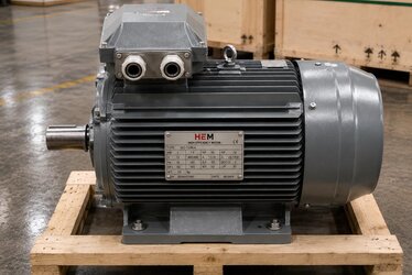
What information should I provide when ordering a spare brake rectifier?
For the correct spare, clearly state the following: the type of the existing rectifier (half-wave/full-wave), the nominal DC voltage and current of the brake coil, the supply AC voltage (such as 230 V or 400 V), whether the fast braking function is required, and the mounting location. With this information you eliminate the risk of a wrong match and ensure a fast, trouble-free replacement in the field. The HEM Motor team helps you identify the correct rectifier from your motor nameplate data.