English
 Türkçe
Summary (TL;DR)
- The flange spigot (register/rabbet) is the machined diameter ring on a cast iron motor's drive-end shield; it seats the motor concentrically onto the pump, gearbox or fan housing and removes alignment error.
- The spigot diameter is machined to the j6 tolerance class per IEC 60072; mating it with an H7 recess gives a vibration-free, runout-free connection.
- A cast iron body is far more rigid than aluminium, so the spigot dimension stays stable over time and concentricity is preserved in heavy duty.
- A wrong spigot tolerance means shaft runout (TIR), bearing overload and early failure. The correct B5/B14/B35 flange dimension must always be confirmed when ordering.
- HEM Motor supplies cast iron motors with IEC-machined spigots from stock, with dimension verification, quotation and manufacturer assurance for error-free replacement.
When mounting an electric motor to a machine, most people only check whether the bolt holes line up. Yet the real alignment of a flange-mounted motor is provided not by the holes but by the machined ring at the centre of the flange. This ring is called the centering spigot, or in technical terms the spigot or rabbet (register). On cast iron bodied motors, this detail forms the foundation of a vibration-free, long-life drive train. The spigot is machined to a precision of microns and, together with the machine recess, directly determines the mechanical quality of the installation. In this article we explain what spigot tolerance means, how it determines concentricity, why a cast iron body is superior for this task, and what to look for when buying the right motor.
What Is the Centering Spigot (Spigot/Rabbet)?
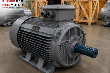
The centering spigot is a precision-diameter ring on the drive-end shield of a B5 or B14 flanged motor that either protrudes slightly from the flange face (male spigot) or is recessed into it (female rabbet). This diameter fits into the matching recess on the pump, gearbox or fan housing the motor bolts to. While the bolts provide axial clamping, the spigot provides the actual centering. In other words, the rotational axis of the motor shaft and the axis of the machine input shaft are brought onto the same line by the spigot. The job of the holes is to hold the motor and react the reaction torque; the job of centering belongs to the spigot.
The IEC 60072-1 standard defines the flange dimensions for each frame size. On a B5 motor, for example, the flange outer diameter (M), the pitch circle diameter (N) and the spigot diameter (P) are standardized. This means motors of the same frame size from different makers can, in theory, fit the same machine. In practice, getting the tolerances right is critical; the standard specifies not only the nominal dimension but also the tolerance class it must be machined to. Even if the nominal spigot diameter is correct, a wrong tolerance class makes the joint either loose or jammed.
Male (Spigot) vs Female (Rabbet)
The motor side usually carries a male spigot, while the machine housing has a matching female recess. In some applications this is reversed. What matters is that the two surfaces seat together with a transition fit. Too loose a fit ruins the centering; too tight a fit makes assembly difficult and causes seizure under thermal expansion. The tolerance class establishes this balance. The cylindrical surface of the male spigot must be perpendicular to the seating face of the flange; if this perpendicularity is off, the motor seats at an angle and an angular alignment error appears even when the spigot diameter is correct.
Spigot Tolerance: j6, H7 and the Mating Logic
Per IEC 60072, the spigot diameter (P dimension) of a motor flange is generally machined to the j6 tolerance class. The mating machine recess should be machined to H7. This j6/H7 pairing creates a slightly tight transition fit: the motor seats by hand or with light force, but the radial clearance is almost zero. The result is near-perfect concentricity.
- j6 (motor spigot): A very narrow, nearly symmetric tolerance band around nominal. Requires precision turning and, where needed, grinding in production.
- H7 (machine recess): A narrow band deviating only in the positive direction from nominal. Lets the recess accept the motor without play.
- Fit type: j6/H7 is a transition fit; it gives some micron-level clearance in some cases and slight tightness in others, but always high centering quality.
- Surface quality: The roughness, burr-freeness and squareness of the spigot surface are as important as the diameter itself.
If the motor spigot is machined below tolerance (too small), radial clearance remains in the recess and the motor shaft runs eccentric to the machine shaft. This eccentricity is measured as shaft runout (TIR — Total Indicated Runout) and directly causes vibration, coupling stress and shortened bearing life. Conversely, if the spigot is well above tolerance (too large), the motor will not enter the recess at all or only by forcing — making assembly impossible or risking cracking the flange. To go deeper into alignment and runout, our guide on soft foot, foot flatness and shaft runout (TIR) alignment is a useful companion.
What Tolerance Means in Practice
Tolerance may sound like an abstract engineering term, but the field consequences are very concrete. A deviation of tens of microns in the spigot diameter is magnified toward the output shaft and can become an eccentricity on the order of a tenth of a millimetre. In a direct-drive (coupled) system this eccentricity applies a varying load to the bearing on every revolution. In a belt-and-pulley system, pulley runout causes belt vibration and premature belt wear. Therefore the correct spigot tolerance is a quality criterion that extends the life not just of the motor but of the entire drive train.
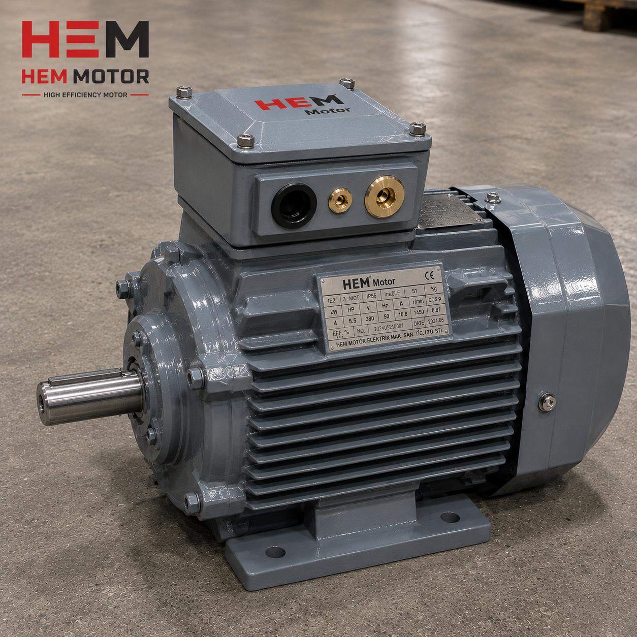
Why a Cast Iron Body Preserves Spigot Precision
It is not enough to hit the spigot tolerance in production; it must be preserved throughout the motor's life. This is where the body material matters. A cast iron body has a much higher modulus of elasticity and mechanical rigidity than aluminium. This means the flange face and spigot diameter do not deform under heavy duty, temperature cycling or coupling/belt forces. Aluminium's coefficient of thermal expansion is roughly twice that of cast iron; this means the spigot diameter shifts more in an aluminium body as temperature changes.
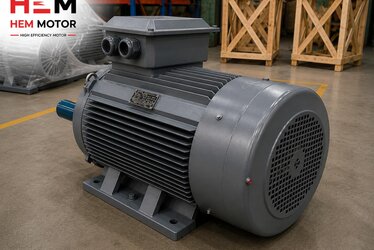
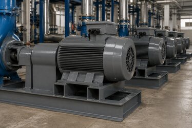
Aluminium-bodied small motors are adequate for light applications, but in crushers, mills, large pumps and continuous process lines, cast iron bodies are preferred. You can review the cast iron motor family and specifications on our cast iron body electric motors product page. In these motors the spigot is machined together with the body in a single setup, so the concentricity between the spigot and the bearing seat is guaranteed at the production stage. The single-setup principle ensures the spigot and the shaft axis are machined to the same reference, keeping the runout of the motor that goes to the field to a minimum.
Spigot, Concentricity and Vibration
When concentricity is lost, the resulting radial eccentricity applies a varying force to the bearing on every revolution. This force appears as a vibration component at 1× running frequency. A high 1× peak in the vibration spectrum often points to an alignment or centering error. Angular misalignment usually raises the 2× component as well. The correct spigot tolerance prevents these errors at their source and greatly reduces the alignment work needed in the field. For vibration acceptance limits, our ISO 10816/20816 vibration and balance acceptance article can be taken as a reference. A quality spigot solves half of the alignment before assembly.
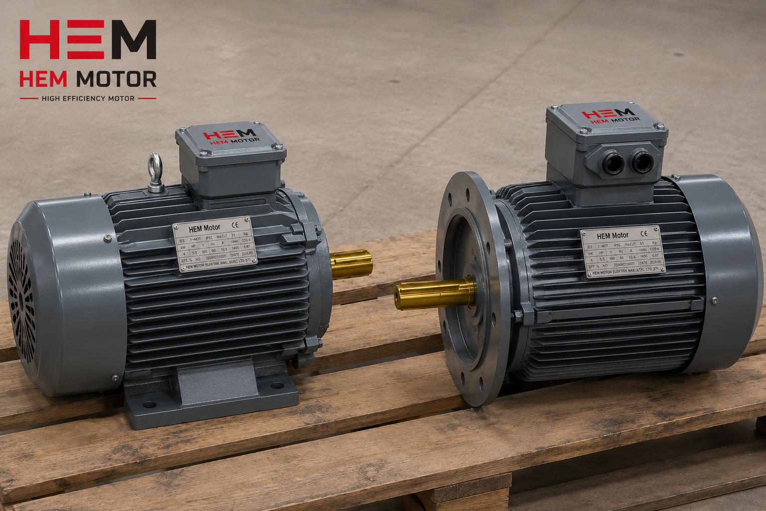
Spigot Dimensions for B5, B14 and B35 Flanges
The spigot diameter varies with the motor's mounting type and frame size. When ordering the right motor, these dimensions must match your machine exactly:
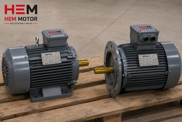
- B5 (large flange): The most common type for direct flange connection to pump, gearbox and fan housings. Its large spigot diameter gives high centering precision and suits larger torque transmission.
- B14 (small flange): Often used in smaller powers, at worm gear reducer inputs. The spigot diameter is small but the tolerance is still critical; on a small diameter even a small deviation grows angularly.
- B35 (foot + flange): Bolts to the floor with feet and to the machine with a flange. Here the spigot handles flange-side centering; the feet provide axial and rotational support. In B35 the consistency between the foot plane and the flange centre is also important.
To clarify the difference between mounting types and the correct connection, our B5 flange electric motors product page can serve as a reference. Trying to fit a B5 motor into a B14 recess or a different frame size makes alignment impossible due to spigot mismatch. Even within the same frame size, the B5 and B14 spigot diameters differ; that is why the mounting type must be stated clearly when ordering.
Spigot Diameter and Shaft Diameter Are Not the Same Thing
A point often confused in the field is that spigot diameter and shaft diameter are separate dimensions. The spigot is the centering ring on the flange; the shaft diameter is the thickness of the output shaft on which the coupling, pulley or gearbox sits. Both dimensions must be verified independently. Even with a correct spigot, the drive element cannot mount if the shaft diameter or key dimension does not match; and even with a correct shaft, the motor cannot be centred on the machine if the spigot does not fit. For correct replacement, both dimensions should be confirmed from the nameplate and the machine catalogue.
Buying Checklist for the Centering Spigot
When buying a motor from stock or to project spec, verify the following regarding the centering spigot:
- Frame size: Whichever IEC 63–355 frame it is, the flange dimensions follow that standard.
- Mounting type code: The B5 / B14 / B35 distinction must be clear; confusion creates spigot mismatch.
- P, N, M flange dimensions: Spigot diameter (P), pitch circle (N) and flange outer diameter (M) must match the machine recess.
- Tolerance class: Check that the spigot is machined to j6 and the surface is clean and burr-free.
- Shaft diameter and key: Even with correct centering, the coupling/gearbox cannot mount if the shaft diameter does not fit.
- Body material: For heavy duty, a cast iron body should be preferred for spigot stability.
At HEM Motor we supply cast iron body electric motors with IEC-compliant machined spigots across a broad frame and mounting range from stock. When replacing a faulty motor in an imported machine, we provide dimension verification and quotation support, so the motor that goes to the field seats correctly on the first attempt with no extra machining needed. Because we work with manufacturer assurance, we can also produce solutions for projects requiring special flange dimensions. Just share your dimensions for current electric motor prices and stock status. The full efficient motor range is available on our IE4 high efficiency electric motors page.
Preventing Spigot-Related Problems at Commissioning
When the motor arrives on site, cleanliness of the spigot surface is the first step of installation. Paint, rust, swarf or burrs left in the recess or on the spigot cause the motor to seat at an angle and create runout even when the spigot tolerance is correct. Cleaning the spigot surface with a fine cloth and a suitable solvent, checking the recess, and applying a light protective film where needed is good practice. After assembly, measuring shaft runout with a dial indicator confirms whether the spigot has done its job. This short check prevents future vibration and bearing failures and lets the motor reach its expected life.
Frequently Asked Questions
Can I still mount a motor whose spigot tolerance does not match?
Even if the bolts physically hold, a loose spigot does not provide centering. The motor shaft runs eccentric to the machine shaft, which means vibration, coupling wear and early bearing failure. The correct solution is to choose a motor of the right frame size with a j6-machined spigot matching the machine recess's H7 dimension. While the recess could be re-machined as a temporary fix, the healthiest approach is to supply a motor whose dimensions are correct from the start.
Why is a cast iron body better than aluminium for the spigot?
A cast iron body is more rigid and deforms less under temperature and mechanical load. Its coefficient of thermal expansion is lower than aluminium's, which means the spigot diameter stays more stable at operating temperature. As a result, concentricity is preserved. In heavy duty, continuous process and high-power applications, cast iron is therefore preferred.
Can I fit a B5 motor into a B14 recess?
No. The spigot diameter, pitch circle and flange outer diameter of B5 and B14 flanges differ, and they do not match mechanically either. Trying to interchange them ruins the centering. You must specify the correct mounting type when ordering and choose the flange that fits the machine recess; if you are unsure, the safest path is to share the machine's flange dimensions and have the correct type confirmed.