English
 Türkçe
When you start an IE4 Super Premium efficiency electric motor directly online (DOL), the very first instant draws an inrush (starting) current far above the rated current. In highly efficient designs the winding resistances are deliberately kept low, so the locked-rotor current (LRA) at start can reach approximately 6-8 times the rated current in most applications. This surge lasts only briefly; however, your switchgear, and especially your contactor, must be able to make and break this current safely without contact welding. In this article we cover the source of high inrush current in IE4 motors, the IEC 60947-4-1 utilisation categories led by the AC-3 category, the correct methods for contactor sizing, and what to watch for so your procurement is right the first time, from both a technical and a purchasing perspective.
Why Is Inrush Current High in IE4 Motors?
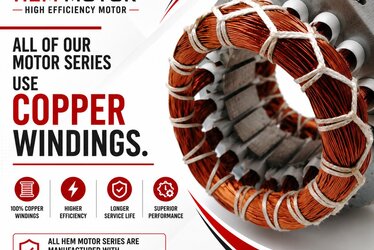
At the moment of starting, an induction motor's rotor is not yet turning, so the relative motion between stator and rotor is maximal (slip = 1). In this state the motor behaves almost like a short-circuited transformer and draws a large current from the supply. This is called the locked-rotor or starting current. In high-efficiency classes such as IE4, manufacturers use higher-grade laminations, more copper and lower-resistance windings to cut losses. Lower resistance reduces thermal loss in continuous running, but it also reduces the effect that limits current at start. As a result, high-efficiency motors can show a similar or even sharper inrush (starting) current profile compared with lower-efficiency motors of equivalent power.
In practice this current is typically in the range of about 6-8 times the rated current; however, this is not a guaranteed spec but a typical band depending on motor design and pole count. The exact value should always be read from the LRA / starting-current ratio on the motor nameplate. If you want a deeper look at starting behaviour in induction motors, our article on asenkron motorda kalkış (yol verme) akımı ve inrush explains this mechanism in detail.
IEC 60947-4-1 Utilisation Categories: AC-1, AC-3 and AC-4
The basis for selecting the right contactor is correctly understanding the utilisation category defined in IEC 60947-4-1. These categories define under what load and which circuit the contactor is expected to switch. Two contactors with the same nominal current value perform completely differently in different categories.
- AC-1: For non-inductive or very low-inductance, resistive loads (heaters, resistors). The current surge is low and it is not suitable for motor starting.
- AC-3 category: Defined for starting squirrel-cage induction motors and switching them off while running. This is the correct category for most motor applications. AC-3 ratings already account for the roughly 6× making current at start.
- AC-4: For much harsher duties such as inching/jogging, plugging (reverse braking) and reversing the direction of rotation. Here the contactor may open and close before the motor reaches full speed, meaning breaking at very high currents. For AC-4 duty the contactor must definitely be upsized.
The most critical point is this: a contactor rated in the AC-3 category for your motor's rated current handles the inrush current without trouble, because the AC-3 classification inherently covers the high making current at motor start and breaking at normal current while running. By contrast, selecting based only on the AC-1 value will cause the contactor contacts to weld during the starting surge and lead to early failure.
Contactor Sizing: The Correct Method
Correct contactor sizing is done according to the AC-3 rated operational current at the motor's operating voltage. A sequential approach is recommended:
- Read the rated current from the motor nameplate (for example the value stated for 400 V) and make sure the contactor's AC-3 rated current at that voltage equals or slightly exceeds this value.
- Always leave a safety margin. Instead of a borderline choice, a one-size-larger contactor offers an advantage in both thermal safety and electrical life.
- If frequent starting (high starts/hour) or AC-4 duty is involved, de-rate the contactor and step up one size.
- Select the contactor in coordination with the thermal overload relay and the fuse/MCCB. The aim is a protection chain compatible with the type 2 coordination concept, so the equipment remains reusable after a short circuit.
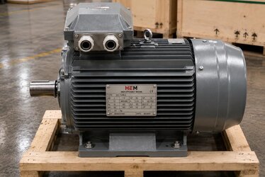
In IE4 motors, having complete and legible nameplate data is the basis of this calculation. With a motor whose rated current, cos φ and LRA values are clearly documented, you size the cable cross-section, fuse and contactor correctly the first time. To see a similar calculation chain for the IE3 class, our article on IE3 motorda anma akımı, kablo, sigorta ve kontaktör seçimi guides you step by step.
Starting Methods That Reduce Inrush Current
Direct online starting (DOL) may not be required in every application. Limiting the starting current benefits both the supply and the contactor life. The main methods:
Direct Online (DOL)
The simplest and most economical method; built with a single main contactor and an overload relay. Preferred at small power ratings and where the supply can withstand the surge. However, the full inrush (starting) current is drawn at start.
Star-Delta
Reduces the starting current to roughly one third. It requires three contactors (main, delta, star) and a timer relay. Common with loads that start unloaded or with low torque, such as pumps and fans.
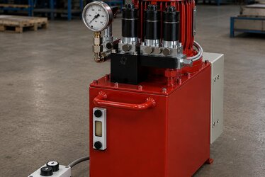
Soft Starter and Variable Frequency Drive (VFD)
A soft starter ramps up the voltage gradually, markedly reducing starting current and mechanical stress. A VFD controls frequency and voltage together, dramatically lowering inrush while also providing speed control. It stands out in conveyors, compressors and variable-speed applications. You can examine the difference between direct online starting and PM-assisted structures in our article on IE4 LSPM şebekeden doğrudan yol verme.
Frequent Starting and Contactor Electrical Life
A contactor's life is expressed by two main parameters: mechanical life (number of no-load switching operations) and electrical life (number of switching operations under load). If the motor starts many times per hour (frequent starting), the contacts close under high inrush (starting) current at each start and wear out. In this case:
- Select a contactor with higher mechanical and electrical durability.
- If conditions in practice approach AC-4 rather than AC-3, upsize it.
- Where possible, limit the current surge with a soft starter or VFD to reduce contact wear.
- Set the thermal relay according to the motor's actual starting time; otherwise you face nuisance tripping or delayed protection.
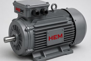
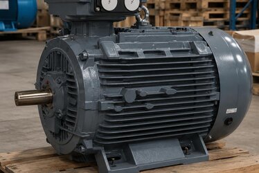
The cast-iron frame, IP55 protection class, class F insulation, 100% copper winding and S1 continuous duty of IE4 motors provide long life under heavy operating conditions; a correctly selected contactor completes that life.
Correct Procurement: Error-Free Selection with Manufacturer Assurance
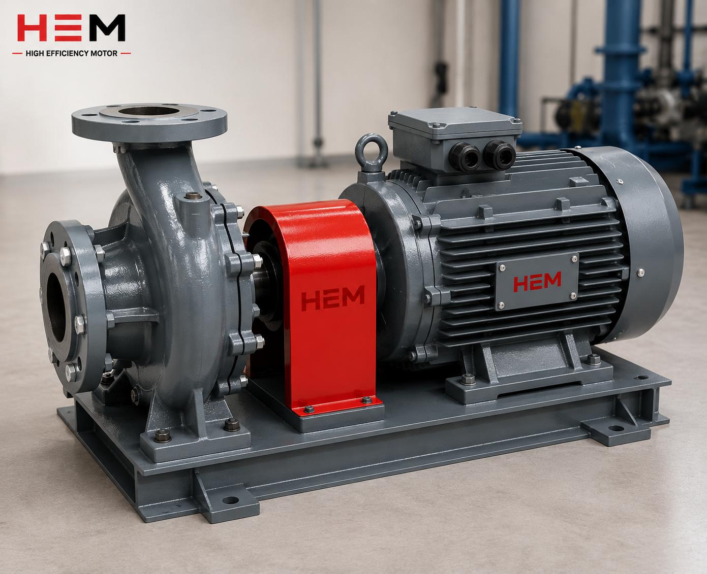
Before connecting a motor to the panel, getting the contactor, cable and fuse selection right prevents wasted time and cost in the field. As HEM Motor, we supply IE4 Super Premium motors from stock in the 0.25-355 kW power range, at 1000/1500/3000 rpm speeds and with B3/B5/B35 mounting options. Because each motor's nameplate documents the rated current, LRA and cos φ values, the buyer sizes the contactor/cable/fuse correctly the first time.
- Fast delivery from stock: meeting your project schedule without delay.
- Manufacturer assurance: consistency of technical data and sustainable spare-motor supply.
- Technical support during the quotation process for the starting method and contactor category suited to your application.
- Minimising downtime risk on critical lines through spare-motor planning.
You can review our product family for current elektrik motoru fiyatları and stock status. For high-efficiency options, take a look at our IE4 elektrik motorları and IE4 yüksek verimli elektrik motorları categories. For standard industrial applications, our genel maksatlı sanayi tipi motorlar meet your needs.
Coordination of Contactor, Overload Relay and Fuse
In a motor circuit the contactor does not work alone; it forms a whole together with the overload relay and the short-circuit protection (fuse or MCCB). Selecting these three in harmony protects both the motor and the panel. The overload relay detects when the motor continuously draws current above its rated value (for example due to mechanical overload, phase loss or excess load) and trips the contactor open. The short-circuit protection, on the other hand, clears the actual high fault current very quickly. The contactor is responsible for switching the normal operating and starting current; clearing a short circuit is not its job.
This is where the type 2 coordination concept comes in. In type 1 coordination, damage to the equipment after a short circuit is permitted; only the absence of danger is expected. In type 2 coordination, the contactor and relay must remain reusable after a short circuit, apart from light welding on the contacts. In industrial facilities, type 2 coordination is usually targeted to shorten downtime. When performing contactor sizing, verifying these coordination tables from the manufacturer's data prevents surprise failures in the field.
The setting range of the overload relay should cover the motor's rated current and have a delay characteristic suited to the starting time (usually class 10 or class 20). For frequent and long starts, selecting a higher tripping class prevents nuisance tripping. For this chain to be set up correctly, the rated current and LRA values on the motor nameplate must be clear.
Voltage Drop, Cable Cross-Section and Heating Inside the Panel
High inrush (starting) current affects not only the contactor but also the supply line. The large current drawn at start causes a temporary voltage drop in the cables and the supply network. This voltage drop can affect other devices fed from the same busbar and may even reduce the motor's starting torque. Therefore, while the cable cross-section is selected according to the continuous rated current, the temporary voltage drop caused by the starting current should also be taken into account.
Over long cable distances the voltage drop is more pronounced; in such cases stepping up to a larger cable cross-section or limiting the starting current with a soft starter/VFD is the solution. Heating inside the panel is also an important issue: the contactor, relay and cables warm up under load. If panel ventilation is insufficient, the ambient temperature reduces the contactor's rated value (de-rating). Just as an IP55 IE4 motor is resistant to field conditions, the equipment inside the panel must also be evaluated according to the ambient temperature.
- Determine the cable cross-section by both the continuous current and the voltage drop limit.
- Verify starting performance on long lines by calculating the voltage drop.
- If the panel ambient temperature is high, de-rate the contactor and relay values accordingly.
- On VFD supplies with high harmonics, evaluate cable and filter selection separately.
A correctly designed supply and switchgear chain turns the high-efficiency advantage of the IE4 motor into real savings in the field. Incorrect sizing, on the other hand, can overshadow the efficiency gain by causing nuisance tripping, contact wear and inefficient operation.
Choosing the Starting Method by Application
The right method depends on the character of the load. For loads with a quadratic torque characteristic such as pumps and fans, star-delta or a soft starter is often sufficient. For loads requiring high inertia or high starting torque such as conveyors, crushers and mills, a VFD both limits the starting current and provides the required torque in a controlled manner. In systems that switch on and off frequently, limiting the current surge with electronic methods to preserve contactor life also makes economic sense.
- Low inertia, unloaded start: DOL or star-delta may be sufficient.
- Smooth start and mechanical protection priority: soft starter.
- Speed control and energy saving: with a VFD, the efficiency advantage of the IE4 motor is maximised.
- Very frequent starting: electronic limiting plus a high-durability contactor should be evaluated together.
Frequently Asked Questions
Is the inrush current in an IE4 motor higher than in IE3?
Because IE4 motors use low-resistance windings for high efficiency, their starting current profile can be similar to or slightly sharper than an IE3 motor of equivalent power. For the exact value you should always rely on the LRA / starting-current ratio on the motor nameplate; the typical band is about 6-8 times the rated current.
Can I select the contactor based on the AC-1 value?
No. For a motor load, the contactor must be selected according to the rated current in the AC-3 category. AC-1 is only for resistive loads and does not account for the starting surge; therefore a contactor chosen on the AC-1 value can have its contacts weld at start and fail early.
How should a contactor be selected for a frequently starting motor?
At a high starts/hour value, the contactor should be stepped up one size for both AC-3 and electrical life, and where possible the inrush should be limited with a soft starter or VFD. This reduces contact wear and extends the switching life.