English
 Türkçe
Press and forging machinery represent one of the most demanding operating environments in the world of industrial drives. In these machines, the motor does not produce a steady, uniform torque; instead it faces sudden impact load spikes that rise and disappear within a fraction of a second. The instant the die strikes the material, the moment the forging hammer hits the metal, or the position where the press approaches bottom dead center, all translate into severe mechanical stress on the drive train. It is precisely here that frame material, shaft strength and bearing selection become far more decisive than the motor's nameplate power.
Many operations look only at the kilowatt rating when selecting a motor for a press or forging application. Yet in these duties the real test is not the average power but the peak torque at the moment of impact, the lateral forces coming from the shaft end, and the frame's ability to hold its shape under vibration. A lightweight aluminium-framed motor, even if its nominal power is sufficient, can enter resonance in this impact environment, lose shaft alignment and prematurely fatigue its bearings. This is why a cast iron frame is the preferred structural solution in heavy impact applications.
In this article we examine, in technical terms, the load profile that presses and forging impose on the motor, the relationship between flywheel and inertia, the concept of overhung radial force coming from the shaft end, bearing life, starting torque, and the correct frame-shaft-coupling combination. Our goal is to help you base your purchasing decision on engineering logic rather than a single number.
Why Is the Load in Pressing and Forging Considered "Impact" Load?
Continuous-duty machines (fans, pumps, conveyors) present the motor with a smooth and predictable load. The load torque rises gradually with speed and becomes stable. Pressing and forging are the exact opposite. During a press cycle, the motor draws relatively low load until the die contacts the material; at the moment of contact, the load torque shoots up to its peak value within milliseconds. This sudden jump is not a classic sine curve but a sharp impact peak.
This impact stresses three separate components simultaneously. The first is the shaft and key connection, where the peak torque creates torsional stress. The second is the bearings, where impact energy is transferred to the race surfaces. The third is the frame, which is continuously loaded by vibration and bending forces. A cast iron frame, thanks to its high modulus of elasticity and internal damping capacity, acts as a skeleton that protects all three of these components.
Peak Torque and Service Factor Relationship
When selecting a motor for impact duty, nominal power alone is insufficient. Peak torque can often reach 1.8 to 2.5 times the nominal torque. Therefore the service factor and transient overload capacity are of critical importance. A motor with a high service factor, F class insulation and 100% copper winding can absorb these repeated impact peaks without overheating or winding fatigue. If you want to study the service factor in more depth, our article on service factor and overload capacity in IE3 motors explains the topic with numerical examples.
Flywheel, Inertia and Softening the Impact
The flywheel is an indispensable component of press and forging machinery. The flywheel stores kinetic energy throughout the cycle and releases it at the moment of impact, reducing the motor's instantaneous power demand. In other words, the higher the inertia of the flywheel, the smaller the motor can be selected, because the bulk of the impact energy comes from the rotating mass. However, this creates a trade-off that complicates the motor's starting behavior.
A large flywheel is a significant inertial mass when it is brought online, and accelerating this mass from zero to nominal speed requires a high starting torque from the motor. If the motor does not have sufficient starting torque, the start-up time lengthens, the winding overheats and thermal protection may trip. For this reason, motor selection for high-inertia loads must be made by evaluating both impact resistance and starting capability together.
We detailed the reflection of the flywheel and inertia relationship in other impact applications such as crushers and stone crushing in our article on motor, flywheel and inertia balance under impact load; the logic overlaps with press applications.
Why Does the Inertia Ratio Matter?
The ratio between the load inertia reflected to the motor shaft and the motor rotor inertia directly affects starting and stopping behavior. If this ratio is too high, the motor struggles to accelerate the load and control becomes unstable. As the flywheel mass grows, this ratio increases; therefore the flywheel selection must be made in harmony with the motor's torque-speed curve. Cast iron framed heavy-duty motors, thanks to their reinforced bearing structure, handle these high-inertia starts more safely.
Overhung Radial Force: The Silent Threat from the Shaft End
In press and forging drives, power is usually transmitted by belt-pulley or chain-sprocket. This form of transmission applies a force to the motor shaft that is not axial but lateral. When the pulley is close to the shaft end, this lateral force is multiplied by its distance from the bearing center, creating a bending moment. This lateral load coming from the shaft end is called overhung radial force in the technical literature and is one of the biggest determinants of bearing life.
As belt tension increases or pulley diameter decreases, this radial force grows. In an impact application, the dynamic component created by the press impact is added to the belt tension. As a result, the bearings must carry both the constant belt load and the repeated impact load. This is why, in these motors, the overhung radial force calculation is a more critical engineering step than selecting the power.
- Pulley diameter: A small-diameter pulley produces a higher radial force to transmit the same torque; the largest possible pulley diameter should be preferred.
- Pulley position: The pulley should be placed as close as possible to the bearing shoulder rather than the shaft end, so that the bending lever is shortened.
- Belt tension: Excessive tension unnecessarily enlarges the radial load; it should be kept within the manufacturer's tolerance.
- Bearing class: Reinforced, heavy-duty bearings should be preferred in impact environments.
- Shaft diameter: A sufficient shaft diameter limits bending stress and deflection.
We covered how shaft diameter, key and coupling matching should be selected under these forces in detail in our guide on shaft diameter, key and coupling selection in cast iron motors.
The Mechanical Superiority of the Cast Iron Frame
Cast iron is a material composed of an iron-carbon-silicon combination that has excellent vibration damping properties thanks to its graphite structure. This property is invaluable in impact applications. In a press or forging machine, the motor is continuously exposed to micro-vibrations; the cast iron frame converts this vibration energy into heat through internal friction, damps it and reduces the risk of resonance.
Rigidity is the second major advantage. A high modulus of elasticity allows the frame to maintain its shape under load. This guarantees that shaft alignment is not disturbed, the bearing bores remain centered and the belt alignment does not change. A motor that drifts out of alignment shortens both bearing life and belt life. In high-amplitude impact applications such as forging and pressing, this dimensional stability directly affects operating cost.
Our article on impact, rigidity and impact, rigidity and vibration behavior in cast iron motors, which addresses the performance of cast iron at a more fundamental level, forms the theoretical basis of this article.

The Role of IE3 and IE4 Efficiency Classes
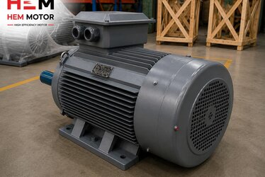
In impact applications, high efficiency does not only mean energy savings. An IE4 Super Premium class motor, because it operates with lower losses, heats up less under the same load. This thermal advantage provides a critical buffer in handling the heat load created by repeated impact peaks. A cooler-running motor preserves its winding insulation and bearing grease for longer. The HEM Motor product range offers IE3 Premium and IE4 Super Premium options from 0.55 kW to 355 kW, with 100% copper winding and F class insulation.
Mounting Type, IP Protection and Operating Environment
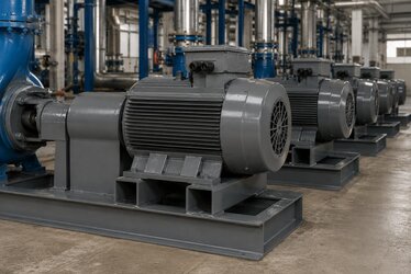
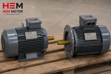
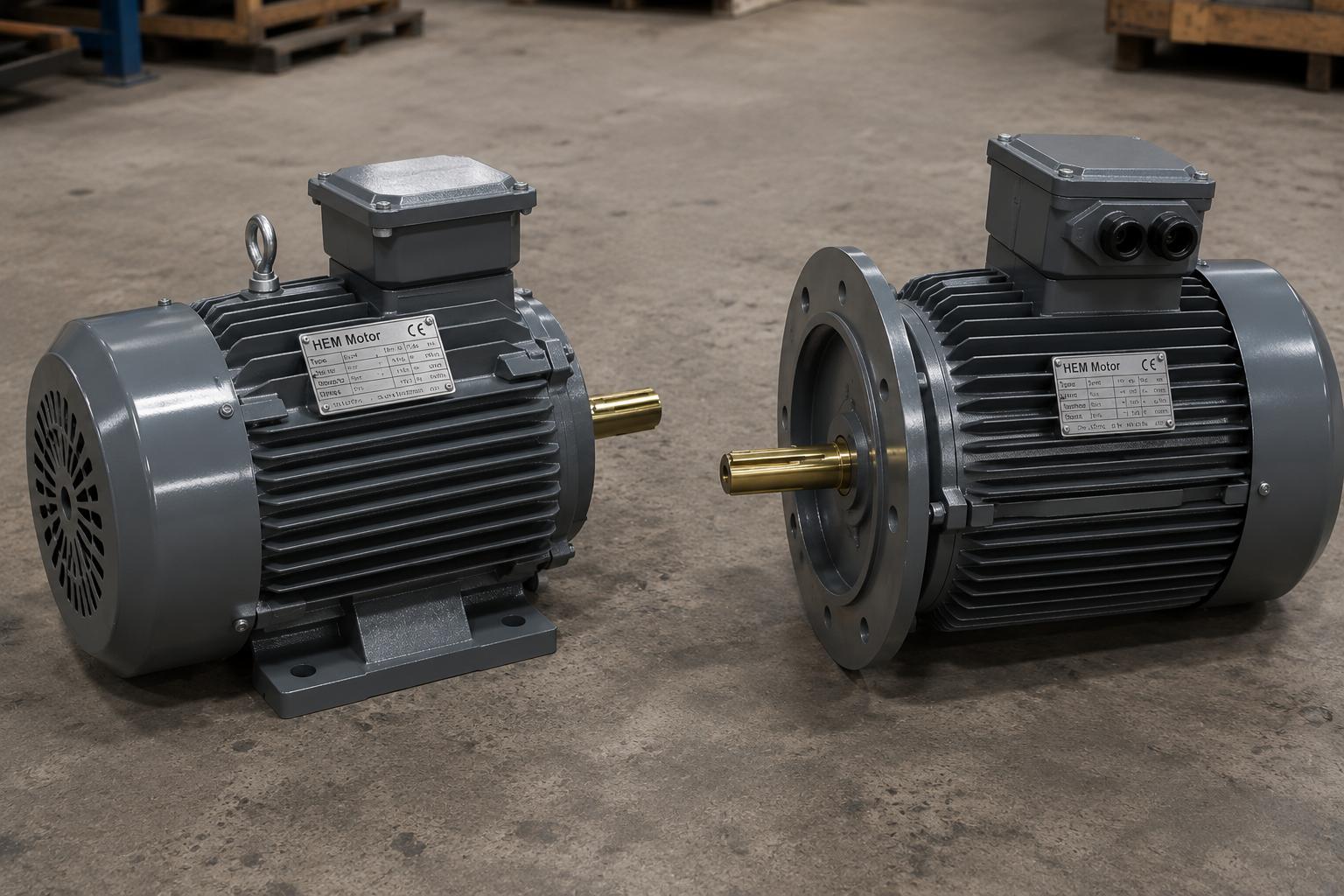
Press and forging workshops are dusty, hot and vibrating environments. The motor must be properly protected against this environment. IP55 protection class offers a safe barrier against dust accumulation and water splashing. The mounting type is selected according to the drive geometry: foot-mounted B3 is generally preferred in belt-pulley drives, while B5 large flange or B35 foot+flange combinations are preferred in directly coupled transmissions.
- B3 (foot-mounted): The classic solution in belt-pulley drives, where the radial load is transferred to the floor through the feet.
- B5 (large flange): For directly coupled press drives where axial alignment is critical.
- B35 (foot+flange): For high-torque installations requiring both foot support and flange connection.
- B14 / B34: For gearmotor combinations requiring a compact layout.
Frame sizes are offered in a wide range from IEC 56 to 355L; the 1000, 1500 and 3000 rpm speed options are determined according to the cycle speed of the press and the flywheel design. Correct mounting and speed selection also positively affect the distribution of overhung radial force.
A Practical Checklist for Selecting the Right Motor
When selecting a motor for your press or forging application, we recommend evaluating the following steps in order. This approach optimizes both the initial investment and the long-term operating cost. You can review our product pages for current electric motor prices and options.
- Determine the peak torque and impact frequency; base your decision on the peak value, not the nominal value.
- Account for the flywheel inertia to derive the start-up time and the starting torque requirement.
- Calculate the overhung radial force from the belt-pulley geometry and compare it with bearing life.
- Consider one frame size up for sufficient service factor and thermal reserve.
- Verify the shaft diameter, key and coupling matching according to torsional stress.
- Select the IP protection and efficiency class (IE4 is preferred) according to the environmental conditions.
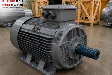
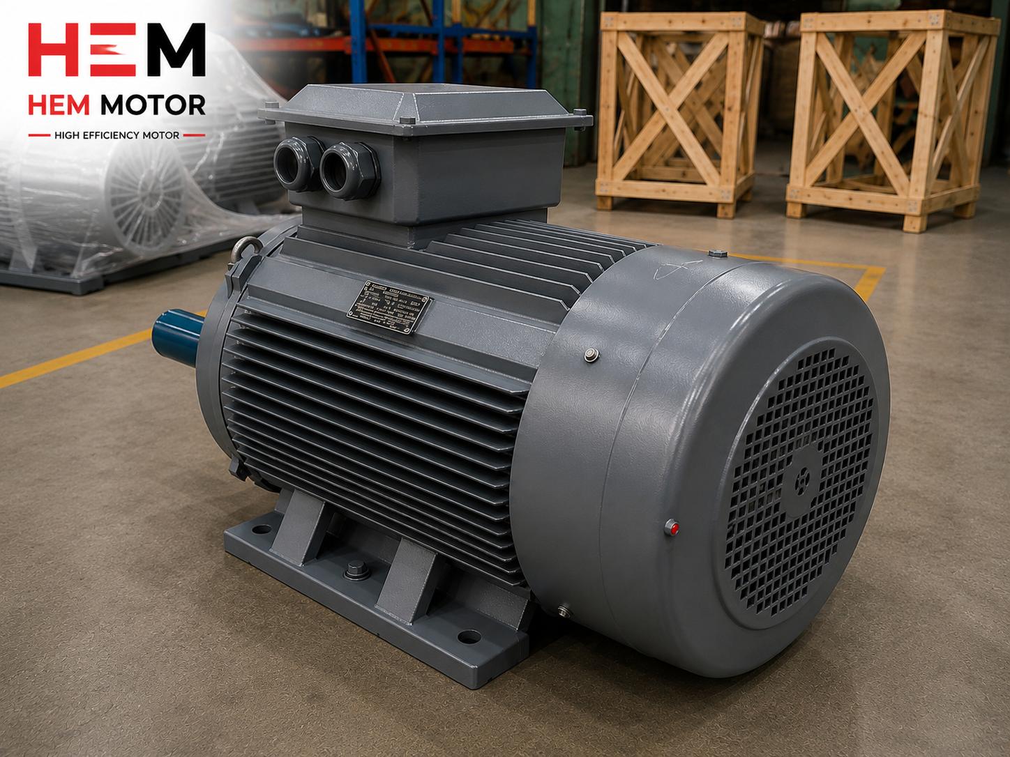
HEM Motor's Cast Iron Frame Electric Motors series is designed for these demanding applications with heavy-duty bearings, a rigid frame and a high service factor. A correctly selected motor reduces the downtime of your press line and lowers maintenance cost.
Frequently Asked Questions
Why should a cast iron frame be preferred over aluminium for press applications?
Because in applications such as pressing and forging, the motor is continuously exposed to impact load and vibration. A cast iron frame, thanks to its high modulus of elasticity and the internal damping provided by its graphite structure, absorbs vibration, maintains shaft alignment and reduces the risk of resonance. Although an aluminium frame is light and efficient, its dimensional stability and vibration resistance lag behind cast iron in these impact environments.
How does overhung radial force affect bearing life?
Overhung radial force is the lateral load coming from the shaft end in a belt-pulley drive, and it loads directly onto the bearing races. The higher this force, the greater the contact stress on the bearing and the shorter the fatigue life. Increasing the pulley diameter, moving the pulley closer to the bearing shoulder and keeping the belt tension within the manufacturer's tolerance reduce this force. In impact applications, reinforced heavy-duty bearings carry this load safely.
Can I select a smaller motor when using a flywheel?
Partly yes. The kinetic energy stored by the flywheel covers most of the instantaneous power demand at the moment of impact, which allows a smaller motor to be selected in terms of continuous power. However, a large flywheel means high inertia and the motor needs sufficient starting torque to accelerate this mass. Therefore the motor must be selected by evaluating both continuous power and starting capability together.