English
 Türkçe

The bearing arrangement in large-frame cast iron electric motors is a critical design decision that directly determines motor life, vibration behaviour and the reliability of the coupled system. Especially at high powers, with long shafts and continuous duty operation, the shaft expands axially as temperature rises; a bearing arrangement designed without accounting for this axial thermal expansion leads to bearing overload, premature failure and noise. This is exactly where the concept of locating (fixed) and floating bearing arrangement becomes essential.
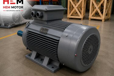
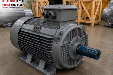
In this article we examine, from both a technical and a sales perspective, why one bearing is axially fixed while the other is allowed to slide in large-frame cast iron motors, the roles of the drive end (DE) and non-drive end (NDE), the bearing types used, and the logic of correct selection and correct ordering or replacement. At HEM Motor, one of the reasons we prefer a cast iron body for large frames in our IE3 Premium and IE4 Super Premium asynchronous motors — across a power range from 0.55 kW up to 355 kW — is precisely this management of bearing load and axial expansion.
Understanding the bearing arrangement correctly matters not only for maintenance teams, but for everyone who buys, engineers or orders a replacement motor. A motor supplied with the wrong bearing type or the wrong fixing logic will never deliver its true life, even if it runs mechanically.
Axial Expansion: Why the Two Bearings Cannot Be Identical
The shaft of an electric motor heats up while running. Although the thermal expansion coefficient of steel may seem small, when shaft length and temperature difference are considered together in large-frame motors, a noticeable axial elongation of the shaft between the two bearings is inevitable. If you fully fix the bearings at both ends of the shaft to the housing, the elongation has nowhere to go when the shaft expands.
In that case the shaft generates an axial force between the inner and outer rings of the bearings. This force strains the raceways of the deep groove ball bearings, breaks down the lubricant film, and increases friction and temperature. The result is rising bearing temperature, shortened grease life and, ultimately, premature bearing failure. This is why the engineering solution is to keep one bearing axially locating (fixed) and let the other float axially so the shaft can "breathe".
What Does the Locating Bearing Do?
The locating bearing determines the axial position of the shaft. Its outer ring is gripped in the bearing housing and its inner ring on the shaft in both directions, so the shaft cannot move axially at this point. The locating bearing both maintains the magnetic centre of the rotor and reacts the axial forces coming through the coupling. The drive end (DE) bearing is usually designed as the locating bearing because it is the side where the coupling and load are connected. This keeps the end position of the shaft defined relative to the load and preserves coupling alignment.
What Does the Floating Bearing Do?
The floating bearing compensates for the thermal elongation of the shaft. In this bearing the inner ring is usually fixed to the shaft, but the outer ring is allowed to slide axially within the bearing housing; or a bearing type whose inner and outer rings can shift axially relative to each other (for example a cylindrical roller bearing) is selected. As the shaft heats and expands, this sliding clearance in the floating bearing absorbs the elongation without trouble. The non-drive end (NDE) is most often arranged as the floating bearing.
Roles of the DE and NDE Bearings
The two bearings of a motor are never identical; each has a different job. The drive end (DE) is where the shaft extends outward and the load is connected via coupling, pulley or gear. The non-drive end (NDE) is usually where the fan and fan cover are located, transferring no work outward.
- DE bearing (locating): Defines axial position, carries radial and axial loads from the coupling, maintains the rotor magnetic centre.
- NDE bearing (floating): Carries only radial load, compensates shaft thermal elongation by axial sliding, accumulates no axial force.
- At high powers: Above 200 kW, a cylindrical roller bearing on the DE side for heavy radial loads may be combined with a separate ball bearing for axial location.
- In vertical mounting: The shaft loads its own weight axially onto one bearing; here the locating/floating logic differs from horizontal mounting.
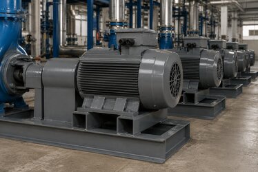
This division of roles becomes especially pronounced in large-frame cast iron motors. As the frame grows, the shaft diameter (for example about Ø100 mm in a 355 frame), shaft length and carried load increase, making bearing selection more critical. The topic of cast iron motor shaft, key and coupling matching is directly related to this bearing arrangement, because the axial and radial behaviour of the coupling determines the load carried by the locating bearing.
Bearing Types and Selection Logic
The locating/floating arrangement is set up differently depending on the bearing type used. The most common approaches in large-frame cast iron motors are:
Deep Groove Ball Bearing
The deep groove ball bearing is the most common type, able to carry both radial and limited axial loads. At medium powers ball bearings are used at both ends; one is axially fixed (held in both directions) and the outer ring of the other is released to allow sliding. It is preferred for quiet running and low friction.
Cylindrical Roller Bearing
For large motors with high radial loads, a cylindrical roller bearing is used on the DE side. By its construction the inner and outer rings can slide axially relative to each other, which makes it a natural floating bearing. Its very high radial capacity lets it carry heavy coupling and pulley loads.
Angular Contact Ball Bearing
In applications where axial load is dominant, angular contact ball bearings may be used in a paired (back-to-back) arrangement. These bearings operate under a defined preload and keep the shaft position precise, especially in vertical mounting or under high axial thrust.
Preload, Spring Washer and Vibration Control
Even though the outer ring of the floating bearing is allowed to slide, the bearing should not run with play; it should operate under a defined minimum axial force. For this reason a preload spring washer is usually placed behind the floating bearing. This spring applies a light, continuous axial pressure to the bearing, ensuring the balls seat correctly in their raceways, maintaining the sliding clearance and reducing vibration at the same time.
Correct preload prevents bearing noise and micro-sliding (false brinelling). If the preload is too low, micro-movements occur within the bearing; if too high, friction and temperature rise. The high rigidity and mass of the cast iron body act here as a natural vibration damper, which is another reason cast iron is preferred at high powers. For those who want to explore the relationship between bearing life and insulation in more depth, our content on asynchronous motor bearing types, life and insulated bearings is a good complement.
Bearing Arrangement Difference in Horizontal and Vertical Mounting
How the bearing arrangement is set up depends on the mounting (connection) type of the motor. In horizontal mounting the weight of the shaft loads the bearings radially, and the axial load comes mainly from the coupling and thermal expansion. Here a classic locating/floating arrangement is sufficient.
In vertical mounting, the weight of the shaft and rotor loads one bearing directly in the axial direction. In this case the lower or upper bearing must be selected of a type that can carry this continuous axial load (for example angular contact or a special thrust bearing). Therefore, when placing a motor into a vertical application, you must question not only the mounting flange but also whether the bearing arrangement suits the vertical load.
Coupling Alignment and Axial Position
Because the locating bearing determines the axial position of the shaft, coupling alignment is directly related to this bearing. If an axial tension (preload) is left in the coupling assembly, the entire force loads onto the locating bearing and strains it. The correct practice is to leave the axial gap recommended by the manufacturer between the coupling halves and to align the motor and the driven machine precisely, both radially (parallel) and angularly.
Misalignment loads variable forces onto both the locating and floating bearings, increasing vibration and seriously shortening life. For this reason, methods such as laser alignment are strongly recommended when commissioning a high-power cast iron motor. To define the right specifications when selecting or replacing a motor, you can review our product families from our electric motor prices page and clarify the body and bearing structure suitable for your project.
Ordering and Spares: How to Specify the Right Motor?
When ordering a large-frame cast iron motor or replacing a faulty one, power (kW) and speed (rpm) data alone are not enough. The following bearing-related information should also be clarified:
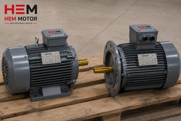
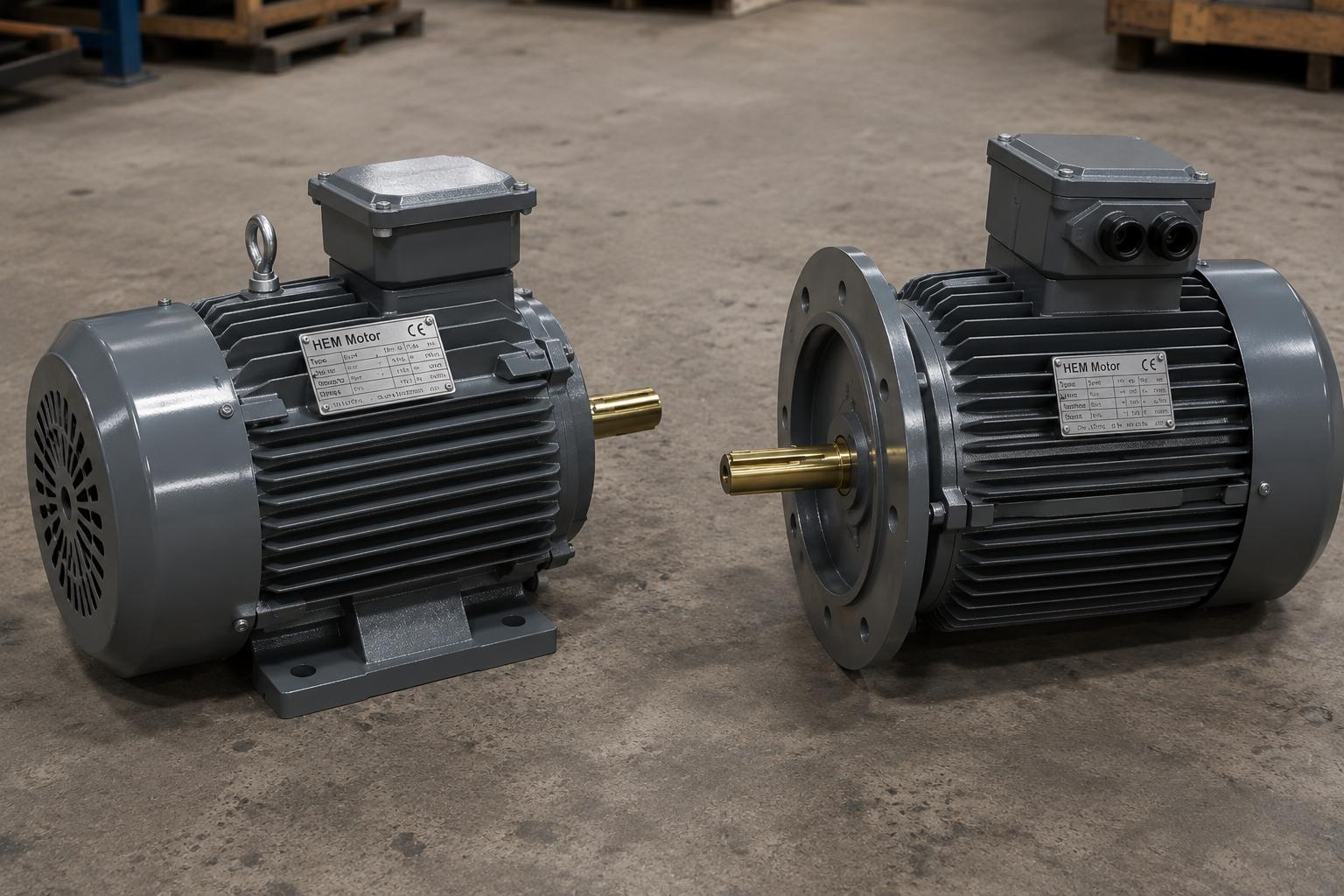
- Mounting type: Connection type such as B3, B5, B35, B14, B34 and horizontal/vertical position.
- Bearing types: Whether ball or roller bearings are used at the DE and NDE.
- Axial load condition: Expected axial force from coupling, pulley or vertical load.
- Shaft diameter and length: Frame size (IEC 56-355) and shaft diameter (for example Ø100 mm in a 355 frame).
- Insulation and protection class: IP55 (IP65/IP66 on request), insulation class F (H on request), S1 continuous duty.
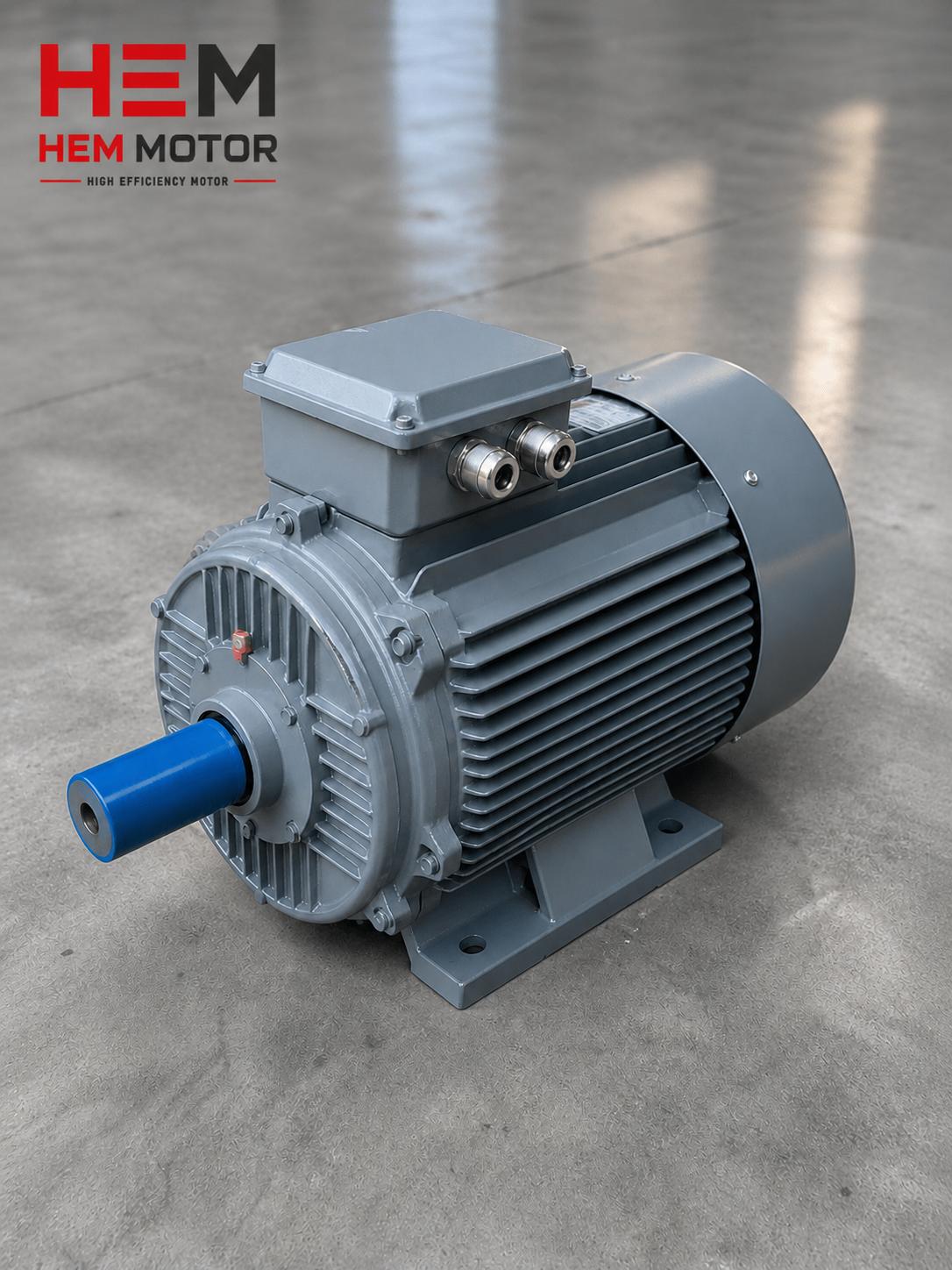
The cast iron body motors we manufacture at HEM Motor are designed for long, reliable operation at high powers thanks to 100% copper windings, reinforced bearing structure and high vibration resistance. In applications seeking high efficiency, it is possible to combine energy savings with bearing reliability using IE4 electric motors. A motor supplied with the correct bearing arrangement specified delivers its true performance, both mechanically and electrically.
Frequently Asked Questions
Why is the locating bearing usually placed on the drive end (DE)?
The drive end is where the coupling and load are connected. Because the end position of the shaft must remain defined relative to the load, coupling alignment must be preserved, and axial forces must be reacted, the locating bearing is usually placed on the DE side. This keeps the shaft "reference" point fixed on the load side, while thermal elongation is compensated at the NDE side where the floating bearing is.
What happens if I fix both bearings?
If you fix both bearings axially, the elongation has nowhere to go when the shaft heats and expands, and high axial force builds up on the bearings. This breaks down the lubricant film, increases friction and temperature, shortens grease life, and ultimately causes premature bearing failure. That is why one bearing must always be left floating.
Why are cylindrical roller bearings preferred in high-power motors?
A cylindrical roller bearing can carry much higher radial loads than a deep groove ball bearing, which is an advantage at high powers with heavy coupling and pulley loads. Moreover, because its inner and outer rings can slide axially relative to each other, it acts as a natural floating bearing and compensates the shaft's thermal elongation without trouble.