English
 Türkçe
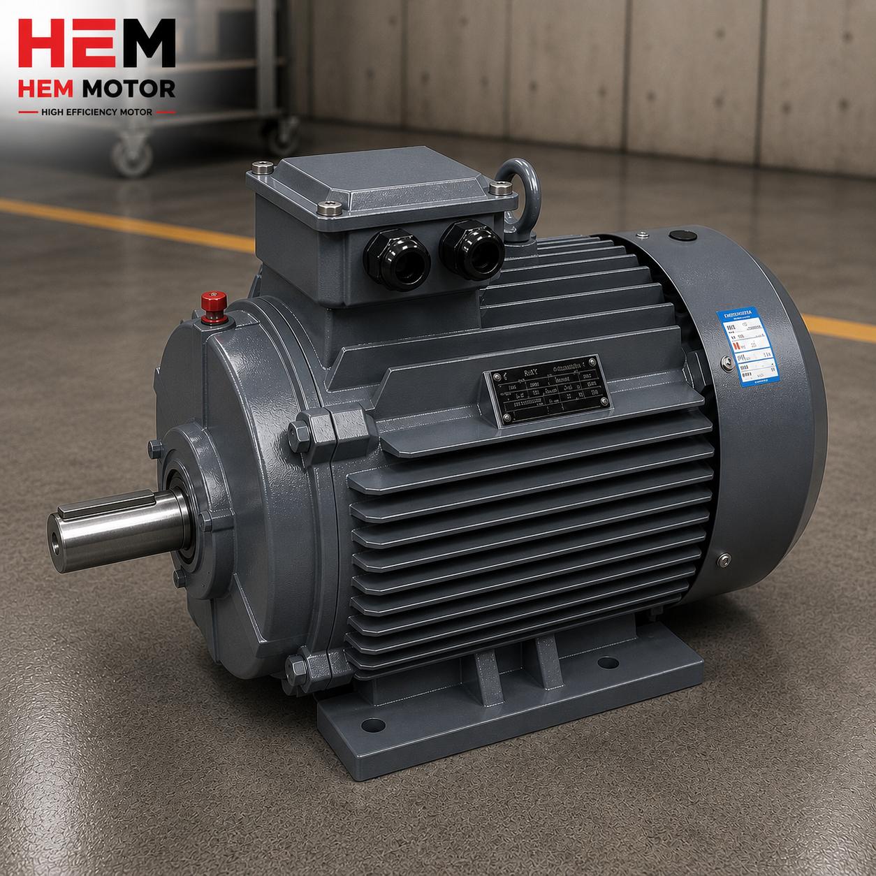
Lifting a heavy cast iron electric motor may look at first glance like a simple crane job, but it is in fact a safety matter that must rest on the right calculation and the right equipment. The lifting eyebolt (DIN 580) threaded into the motor housing is a reliable lifting point when used correctly; when used incorrectly it turns into a weak link that endangers both the equipment and the workers. In this article we examine, with technical detail, the load-bearing logic of the DIN 580 eyebolt, the importance of the sling angle, the motor's center of gravity and the correct lifting method.
The most critical point is this: the rated load of a DIN 580 eyebolt applies only to a perfectly straight-up pull (axial load). As the sling rope deviates from the vertical, the angle of the load on the eyebolt changes and the safe load the eyebolt can carry drops fast. At angles above 45 degrees, the eyebolt capacity can fall to a quarter of its rated value. Lifting from two points without being aware of this is a mistake that can lead to serious accidents.
A cast iron housing provides a great advantage in holding the eyebolt thread securely; but this advantage applies only when the eyebolt is fully and correctly threaded. As HEM Motor, we provide the housing type, motor weight and recommended lifting point information to our customers at the ordering stage, so that a safe handling plan can be set up correctly from the start in the field.
What a DIN 580 Lifting Eyebolt Is and How It Works
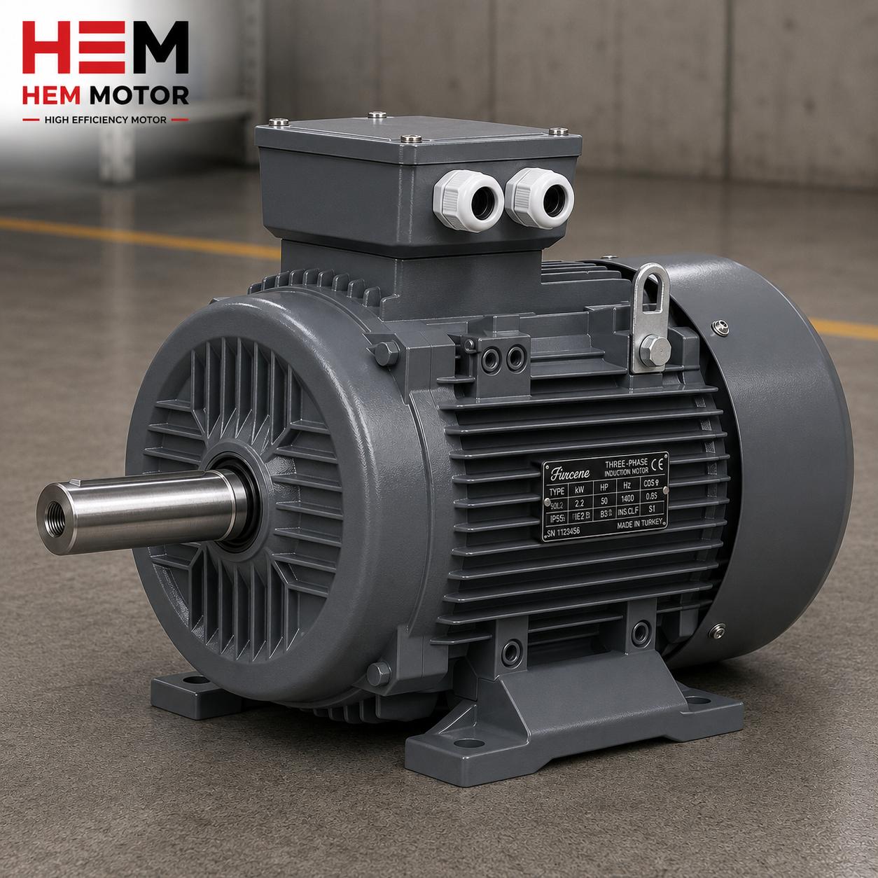
DIN 580 is a German standard that defines the dimensions, material and load capacities of metric threaded eyebolts (lifting eyebolts). These eyebolts are usually made of forged steel and carry the thread size and class information on them. In electric motors, they create a lifting point by being threaded into the tapped holes at the top of the motor housing.
The basic parts of a DIN 580 eyebolt are:
- Threaded body: The part threaded into the tapped hole in the motor housing. It must seat fully on the bearing surface.
- Ring: The closed loop through which the sling hook or rope passes.
- Shoulder (bearing surface): The full contact surface between the eyebolt and the housing; this surface must seat fully for the load to be transmitted correctly.
The rated load marked on the eyebolt applies to an axial (straight-up) pull. When the eyebolt is loaded at an angle, a bending moment is applied to the body of the ring and this reduces the capacity. For this reason, DIN 580 eyebolts are limited to much lower loads in angled lifts.
Why the Sling Angle Reduces Capacity So Much
When lifting from two or more points, the sling ropes form an angle with the vertical axis. As this angle grows, the force on each eyebolt both changes direction and increases. Moreover, the DIN 580 eyebolt is more sensitive to angled loading because a lateral force and a bending moment are applied to the ring body.
The generally accepted safe-use rules are as follows:
- 0 degrees (straight up): The eyebolt can carry its full rated load.
- Up to 45 degrees: The capacity drops markedly; it usually falls to about a third of the rated load.
- Above 45 degrees: The capacity drops much faster and can decline to a quarter level.
For this reason, when lifting from two points, the sling angle should be kept as narrow (as close to vertical) as possible. The practical way to do this is to use longer sling ropes or to keep the ropes vertical with a lifting beam. Keeping the angle under control extends the life of both the eyebolts and the ropes and makes the lift safe. Because of the cosine effect of the angle, even small increases in the angle quickly increase the real force on each rope; so the angle should be determined by measurement, not by guesswork.
Where the Motor's Center of Gravity Is
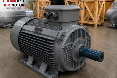
The center of gravity of an electric motor is not at the exact middle of the housing. While the heaviest components of the motor, the lamination stack, the windings and the rotor, are concentrated toward the shaft side, the terminal box adds extra weight to one side. For this reason, the center of gravity usually shifts toward the shaft and terminal box side.
Knowing the center of gravity correctly is critical for a balanced and safe lift:
- If you are lifting from a single eyebolt, the eyebolt must be directly above the center of gravity; otherwise the motor will tilt sideways while suspended.
- If you are lifting from two eyebolts, the load may not be distributed equally; the eyebolt closer to the center of gravity carries more load.
- If the motor tilts slightly when suspended, the center of gravity is not below the lifting point; in this case the rope lengths must be adjusted to achieve balance.
For this reason, the motor's center of gravity and recommended lifting points must be known before lifting. This information should be evaluated at the motor selection and installation planning stage. For the lifting behavior of different housing types, our electric motor frame types and IEC dimensions guide is a useful resource.
The Advantage of the Cast Iron Housing in Holding the Eyebolt
Cast iron (grey iron) housings hold the eyebolt thread much more securely than aluminium housings. This is because of the high compressive strength of cast iron and the solid contact area formed at the thread surface. However, certain conditions must be met to fully benefit from this advantage:
- Full threading: The eyebolt thread must be threaded all the way into the tapped hole in the housing and the shoulder surface must seat fully on the housing. A half-threaded eyebolt carries the load with only part of the threads and risks failure.
- Correct thread size: The eyebolt thread size must match the hole in the housing exactly. Forcing or using an adapter is unsafe.
- Clean threads: There must be no chips, dirt or damage on the threads.
- Undamaged eyebolt: An eyebolt that has previously been overloaded, bent or cracked must never be used.
When the solid structure of the cast iron housing is combined with a correctly threaded eyebolt, it forms a reliable lifting point. For the other properties of the housing material, you can review our cast iron vs aluminium motor housing article.
Step-by-Step Checklist for Safe Lifting
To lift a cast iron motor safely, the following steps must be followed:
- Find out the weight: Confirm the net weight of the motor and select the lifting equipment accordingly.
- Check the eyebolt: Make sure the rated load of the eyebolt meets the motor weight even in an angled lift. If in doubt, use a higher-capacity eyebolt.
- Thread fully: Thread the eyebolt all the way until the shoulder seats on the housing.
- Limit the sling angle: When lifting from two points, keep the angle the ropes make with the vertical below 45 degrees; use a lifting beam if possible.
- Balance the center of gravity: Lift the motor slightly into the air and check its balance; if it tilts, lower it and adjust the ropes.
- Do not apply side load: Do not apply a sideways pull to a single eyebolt; a single eyebolt is only for a straight-up pull.
- Use certified equipment: The load certificates of the ropes, hooks and slings must be valid.
These steps prevent both damage to the motor and occupational safety accidents. The lifting point information, together with the housing type, should be clarified at the motor order and quote stage.
What Information HEM Motor Provides at the Ordering Stage
Safe handling begins with the right information. As HEM Motor, for the cast iron motors in our stock we provide the following information at the ordering stage:
- Net motor weight: The basic data for selecting the lifting equipment and eyebolt.
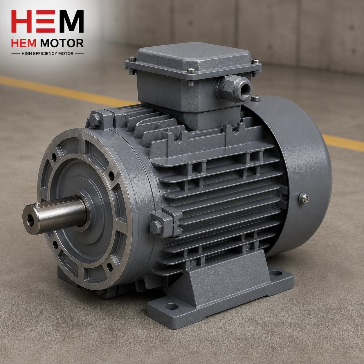
- Housing type and mounting: Foot-mounted (B3), flange-mounted (B5) or combined mounting information.
- Recommended lifting point and eyebolt size: The suitable tapped hole on the housing and the suitable DIN 580 eyebolt size.
- Guidance on the center of gravity: The direction to watch for a balanced lift.
This information allows the team in the field to set up the lifting plan correctly from the start and protects both the equipment and the workers. Correct supply covers not only the motor itself but also the knowledge to put it safely into place.
For current electric motor prices, stock availability and technical data requests, you can visit our electric motor prices page. From our wide cast iron motor stock, we provide fast supply and safe delivery with correct lifting point information; you can request a quote from us for the motor that suits your needs.
Frequently Asked Questions
Why does the DIN 580 eyebolt rated load not apply to a two-point lift?
The rated load marked on a DIN 580 eyebolt is determined on the assumption that a perfectly straight-up (axial) pull is applied to the eyebolt. When you lift from two points, the sling ropes form an angle with the vertical and both a tensile and a bending force are applied to the eyebolt. This angled loading seriously reduces the safe carrying capacity of the eyebolt; above 45 degrees the capacity can fall to a quarter of the rated value. For this reason, a higher-capacity eyebolt should be selected in an angled lift or the angle should be narrowed.
Why is it so important to thread the eyebolt fully?
When the eyebolt is not fully threaded, the load is carried by only part of the threads and the shoulder bearing surface does not seat on the housing. In this case the thread is stressed, the stress concentrates and a risk of failure appears. Threading the eyebolt all the way and full contact of the shoulder surface with the housing ensure that the load is distributed evenly over all the threads and the bearing surface. A cast iron housing holds the thread securely, but this confidence applies only with full threading.
Why does the motor's center of gravity shift toward the shaft and terminal box side?
The heaviest parts of the motor, the lamination stack, the windings and the rotor, are concentrated in the shaft region; in addition, the terminal box adds extra weight to one side. For this reason, the center of gravity is not at the exact middle of the housing but shifts toward the shaft and terminal box side. To prevent the motor from tilting when lifting from a single eyebolt, the lifting point must be above the center of gravity; when lifting from two eyebolts, the rope lengths must be adjusted so that the load is distributed in a balanced way.