English
 Türkçe
No matter how well a cast iron electric motor is wound, if the surface its feet sit on and the machining of its foot-mounting holes are not correct, the motor will come back from the field with vibration, bearing wear and premature failure. In practice the motor itself is sound; the problem usually lies in the motor's base seating plane, foot-hole tolerance and the shimming carried out during installation. This article looks at foot-mounting hole machining quality, base flatness, shimming technique and the relationship between vibration and alignment in cast iron motors from a purchasing perspective, explaining which motor you should select on which base and with which mounting tolerance.
Why Does a Cast Iron Body Help With Foot Flatness?
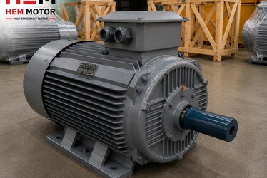
A cast iron body offers far higher mechanical strength and dimensional stability than aluminium. In mounting terms this has a direct payoff: in a cast iron motor with machined feet, all four foot surfaces can be ground to the same plane, and that flatness is retained over time, through thermal cycling and under vibration. A cast iron electric motor is preferred in heavy-duty applications, crushers, stone-crushing plants, compressors and large fan drives for precisely this reason; the body carries reaction forces and belt tension from the base without deforming.
But the body being cast iron is not enough on its own. What matters is that the foot under-surfaces are a machined (ground) reference surface and that all four feet lie in the same manufacturing plane. In a motor from a quality manufacturer, these surfaces are machined in a single setup, and the foot-mounting holes are positioned symmetrically to IEC 60072 mounting dimensions. As a result, when the motor reaches the base in the field, the holes are expected to match the bolts and the feet to seat without gaps.
Why Does Foot-Hole Machining Tolerance Matter?
The foot hole is drilled slightly larger than the bolt body; this clearance gives the lateral shift needed to align the motor. If the hole is too tight there is no room to align; if too wide the motor can slip under bolt preload and produce vibration. A correctly machined foot hole both leaves alignment margin and gives sufficient seating area under the bolt washer. The symmetry of the hole positions is also critical: if the four holes are not to IEC dimensions, shaft alignment between motor and machine is strained from the start.
- Hole diameter tolerance: Enough to leave alignment margin for the bolt, but not so much that the motor slips.
- Hole position (pitch): Conforming to IEC 60072 foot-hole spacing, four holes symmetric.
- Foot surface flatness: All four feet in one plane; a single high foot creates soft foot.
- Surface roughness: The machined surface is smooth enough for full contact with the base.
Base Flatness: It May Be the Frame, Not the Motor, at Fault
The most common field situation is that it is the base, not the motor, that is out of plane. A welded steel frame can bow after welding due to stress relief; a concrete foundation can settle over time; the seating surfaces of an old base can be filled with rust and paint. In that case, even if you fit the highest-quality motor, one or two of the four feet will be left hanging. When you tighten the bolt, the body bends to conform to the base (forced seating), and this bending stress is reflected directly in the bearings, the air gap and shaft alignment.
When evaluating a base, you must check whether the four seating surfaces lie in the same plane. This is done with a straightedge and a feeler gauge to measure gaps between foot and base. If there is a gap, it is filled with a shim, never closed by tightening the bolt.
Soft Foot and Its Relationship to Vibration
If one of the four feet is at a different height from the others, the body is strained when the bolt is tightened; this is called soft foot. Soft foot increases shaft runout (TIR), distorts the air gap and creates magnetic imbalance and mechanical vibration. High vibration shortens bearing life and eventually shows up as "the motor vibrates, heats up, makes noise." Yet the motor itself may be flawless. For this reason, when buying a cast iron motor, choosing a product with machined feet and four-foot flatness guaranteed in production reduces your shimming workload in the field.
Measuring Soft Foot With Feeler Gauge and Dial Indicator
Soft foot cannot be judged by eye; it must be measured. There are two basic methods. The first is the feeler gauge method: with all four bolts tightened, thin blade feeler gauges are slid under each foot and into its four corners to look for a gap. A gap over 0.05 mm is usually a sign of soft foot that needs correcting. Whether the gap is at one corner or across the whole surface also matters; a corner gap means an angular soft foot, while a full-surface gap means a parallel height difference, and the correction differs.
The second and more precise method is a dial indicator four-foot sweep. A magnetic-base dial indicator probe is brought onto the foot, zeroed with all four bolts tight; then the bolt of the foot being measured is loosened one at a time and the amount the foot rises is read. Repeated for each foot, this gives a numerical value of how much each foot is "hanging." A rise of around 0.02 mm is targeted; larger values are corrected with shims. This measurement is data that should be entered into the installation acceptance report and recorded for a guaranteed alignment.
The Four Types of Soft Foot and the Correction Logic
In practice soft foot appears in four forms, each requiring a different solution. Parallel soft foot is when the foot sits parallel to the base but high; a single full-length shim of the right thickness solves it. Angular soft foot is when one edge of the foot touches while the other hangs; here a stepped shim or machining of the foot surface is needed, and filling with thin sheets is wrong. Squishy soft foot comes from rust, paint, dirt or old gasket residue trapped between foot and base; it is solved by cleaning. Induced soft foot arises when piping, conduit or cable strain pulls the body; the source must be found and the strain relieved. A soft foot that is not correctly diagnosed comes back no matter how many shims are added.
Shimming: Right Shim, Right Place, Right Thickness
Shimming is filling the gap between foot and base with stainless steel shims. The aim is twofold: first bring all four feet into the same plane to eliminate soft foot (soft foot correction), then raise the motor relative to the machine to achieve shaft alignment. These two steps must be considered separately; aligning before soft foot is removed leads to alignment that does not hold.
- Use stainless shims: Flat stainless steel shims are preferred; crushed or many thin sheet pieces create "springiness".
- Few shims: Many thin shims stacked under one foot increase flexibility; use as few pieces as possible.
- Full foot contact: The shim must support the entire foot surface; edge support produces vibration.
- Soft foot first, alignment second: Done in order; reversed, the work is repeated.
On a motor with machined foot surfaces and a flat body, shimming takes minutes; on a motor with unmachined or warped feet, the installation crew struggles for hours. So a "cheap body" is misleading in the purchasing decision; installation labour and subsequent bearing replacements raise total cost.
Bolt Tightening Sequence and Torque
After shims are fitted, the foot bolts must be tightened not randomly but in a defined sequence and in graduated torque steps. A cross (star) tightening pattern is used: first all bolts by hand, then to about one third of final torque, then two thirds, and finally to full value in cross order. Pulling a single foot straight to full torque draws the body toward that corner and creates induced soft foot. Holding a dial indicator on the foot during tightening shows live whether the foot lifts as the bolt is tightened; in a good installation the foot should not move throughout tightening. Torque value is set by bolt grade (8.8, 10.9) and thread diameter; lubricated versus dry thread also affects torque. Using a dedicated reference for correct anchor torque is the foundation of a vibration-free fixing.
Thermal Growth and the Hot Alignment Offset
When the motor runs it heats up and its body grows; foot height increases by a few hundredths of a millimetre. The driven machine (especially a pump, compressor or fan) also grows at its own temperature. If the thermal growth of the two machines differs, a system perfectly aligned cold goes out of alignment at operating temperature. For this reason professional installation calculates a thermal growth offset and deliberately aligns the motor with a slight up or down offset while cold, so it comes into true alignment when hot. Because cast iron is a material with a known and stable coefficient of thermal expansion, it makes this calculation predictable; this is a reason to prefer a cast iron motor on large drives.
Correct Motor Selection for Vibration and Alignment
Vibration is usually the sum of three causes: rotor balance, shaft alignment and mounting rigidity. The motor from the manufacturer should have a factory-balanced rotor; but mounting rigidity and alignment depend entirely on field workmanship. Choosing the right motor eases these two field variables:
- Machined feet and flat body: Reduces shimming workload, lowers soft foot risk.
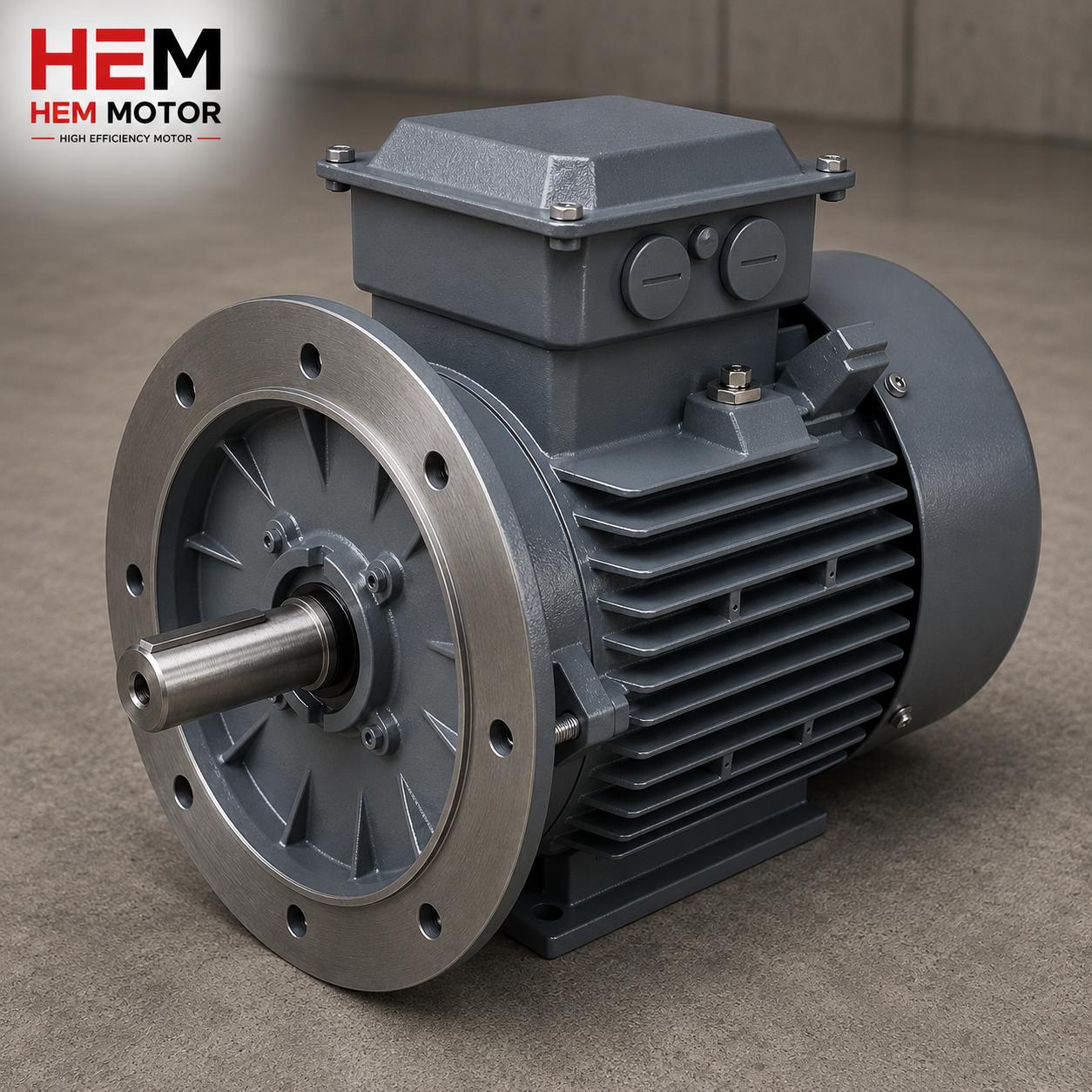
- Correct mounting type: Choose foot (B3), flange (B5) or combined (B35) according to the machine. Our B3 foot-mounted electric motors come with foot and shaft geometry suited to coupling and belt-pulley drives.
- Shaft and key quality: Low shaft runout, standard keyway; this eases alignment in coupled connections.
- Bearing selection: Reinforced bearings for tight-belt applications; margin against vibration.
If you want to go deeper into alignment, our article on soft foot, shaft runout (TIR) and alignment explains the measurement method step by step. For the base and anchoring side, our article on bolt, nut and base mounting with anchor torque covers the tightening values for vibration-free fixing. For coupling type selection, see our guide on flexible and rigid coupling selection with shaft alignment.
Welded Frame or Grouted Concrete Foundation?
The base the motor sits on comes in two main types, and the choice directly determines vibration behaviour. A welded steel frame is a light, portable, quickly installed solution; but it tends to bow due to internal stresses after welding and, if not designed rigidly enough, can resonate at its own natural frequency. If a welded frame is to be used, choose one that is stress-relief annealed, with separately machined mounting pads and reinforced with ribs. A grouted concrete foundation is the most stable solution for heavy, large motors: a steel baseplate is anchored to concrete and the void beneath is filled with a fluid, non-shrink grout. Grout distributes the load uniformly into the concrete, damps resonance and maintains stability over the long term.
In grouting, the grout dam and air-vent holes must be done correctly; otherwise a void remains under the plate and that void becomes a genuine source of base resonance. On large baseplates, machined pad islands between plate and motor foot, and where needed the use of epoxy chocks, provide fuller contact and better damping than conventional metal shims.
Epoxy Chocks, Jacking Bolts and Dowel Pins
On very large machines, or where the base cannot be machined flat, the gap between foot and foundation is filled with pourable epoxy chocks (resin chocks). The epoxy resin takes the exact shape of the foot under-surface to give near hundred-percent contact; it removes the corner-contact problem of metal shims and gives excellent damping under large dynamic loads. To move the motor precisely during alignment, jacking bolts are used; placed at the sides of the feet, these push screws let the heavy motor be shifted horizontally to the micron without a pry bar or hammer. Once alignment is complete, the position is made permanent: dowel pins are drilled and reamed through foot and base together and fitted. The pin ensures that when the motor is later removed and refitted it returns to the same alignment; this significantly shortens alignment time during periodic maintenance.
IEC 60072 Foot Dimensions and the Frame Size Language
The foot-hole positions of cast iron foot-mounted motors are not random but tied to frame size by the IEC 60072 standard. The frame size gives the shaft centre height in millimetres; for example in a 132 frame the shaft axis is 132 mm above the foot base. The standard defines, for that height, the longitudinal spacing of the foot holes (the B dimension), the transverse spacing (the A dimension) and the hole diameter (the K dimension). So one manufacturer's 132M motor and another's 132M motor sit on the same hole pattern; this interchangeability is critical in maintenance and renewal projects.
- Shaft centre height (H): Defines frame size; e.g. 90, 100, 112, 132, 160, 180, 200, 225, 250, 280, 315, 355.
- Foot-hole longitudinal spacing (B): Varies within a frame by S/M/L letters; a longer frame means a wider B dimension.
- Foot-hole transverse spacing (A): Fixed by frame size; sets the bolt spacing on the base.
- Hole diameter (K): Defines the size of the anchor bolt to use; this diameter sets the alignment margin.
At purchasing, not only power and speed but also the frame size letter (S, M, L) matters; because the hole spacing on your existing base was drilled to a specific B dimension. If the wrong letter is chosen, the motor will not seat on the base without drilling new holes. So in renewal purchases the frame size and mounting type code on the existing motor's nameplate (e.g. 160M B3) must be passed on in full.
Belt Tension, Foot Reaction and Corrosion
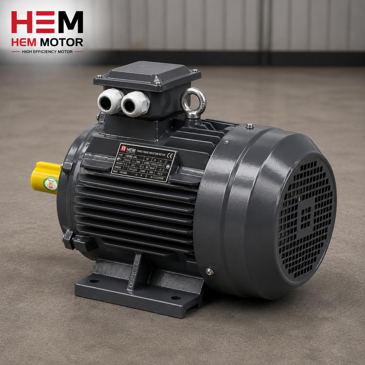
On belt-pulley drives a constant lateral pull is applied to the feet. The tighter the belt, the larger the moment tipping the motor toward the pulley; this moment tries to lift the two feet near the belt and press down the two far feet. Under a body that is not rigid enough or insufficient bolt preload, this leads to foot lift and vibration. A cast iron body is preferred in tight-belt applications because it can carry this reaction moment without bending. During installation the direction of belt tension must be considered and the bolts preloaded accordingly.
Over the long term another silent enemy in the field is foot corrosion. In damp, dusty or chemical environments rust builds up between the foot under-surface and the base; this build-up pushes a once perfectly aligned motor up by hundredths of a millimetre and creates induced soft foot. So before installation both the foot and base seating surfaces should be cleaned to bright metal, a thin corrosion inhibitor applied, and stainless shims used. Inspecting the area around the feet for rust during periodic maintenance prevents vibration faults that are hard to resolve later.
Acceptance and Incoming Inspection: When the Motor Arrives
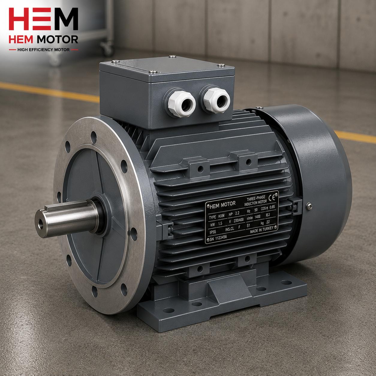
A good incoming inspection catches installation problems that would take hours in the field while the motor is still at the warehouse. When the motor is received, laying a straightedge or surface gauge and feeler gauge on the feet checks whether all four feet are in the same plane. Holding a dial indicator to the shaft end verifies shaft runout (TIR), keyway size and shaft diameter. Nameplate data (power, speed, voltage, frame size, mounting type, IP protection, insulation class) is compared with the order. Terminal box orientation and entry hole position should also be checked; a terminal box facing the wrong way complicates cabling in the field.
- Four-foot flatness: Checked with straightedge and feeler gauge; a single high foot is grounds for return.
- Shaft runout (TIR): Measured with a dial indicator; low runout eases alignment.
- Foot-hole position: Conformance to your base's hole spacing (A/B dimension).
- Nameplate-order match: Power, speed, frame size, mounting type, IP/insulation class.
It is important to consider these inspection steps together with manufacturer assurance: on a motor supplied quickly from stock, with machined feet and faithful to IEC dimensions, the incoming inspection becomes a formality; on a loosely toleranced product, every rejected part means delay in the project. So choosing the right supplier is a matter not only of price but of installation ease and delivery assurance.
Purchasing Checklist: Cast Iron Foot-Mounted Motor
- Body material cast iron; high mechanical strength for heavy duty.
- Foot surfaces machined (ground), all four feet in the same plane.
- Foot-mounting holes to IEC 60072 dimensions, symmetric and toleranced to leave alignment margin.
- Shaft diameter, key and shaft end suited to your machine's coupling/pulley dimensions.
- Factory-balanced rotor; IP55 protection, Class F insulation.
- Stock and lead time: correct frame and speed, in time for the project's installation schedule.
At HEM Motor we offer cast iron motors with machined feet conforming to IEC mounting dimensions in the 0.55 kW – 355 kW range, with the advantage of stock and fast supply. For the right frame size, mounting type and speed, request a quote from our electric motor prices page; we can determine the most suitable motor together according to your project's base and alignment requirements.
Frequently Asked Questions
The foot hole came slightly large, is that a problem?
It is normal for the foot hole to be slightly larger than the bolt; this provides the lateral shift needed for alignment. What matters is that the bolt washer finds sufficient seating area and the bolt is tightened to the correct torque. For oversized holes a wide washer is used. The real risk is the holes not being to IEC dimensions and the four holes not being positioned symmetrically; in that case shaft alignment becomes difficult from the start.
If the base is not flat, can I force the motor to seat?
No. Forcing the body onto the base by tightening the bolt creates soft foot and body strain; this directly damages the bearings and air gap. The correct method is to measure the gap between foot and base with a feeler gauge and fill it with a stainless shim. If the base is seriously bowed, the seating surfaces must be machined (surface ground).
Which motor makes installation easier?
A cast iron motor with machined feet, four-foot flatness guaranteed in production and full compliance with IEC mounting dimensions significantly shortens shimming and alignment time in the field. So in purchasing, not only power and speed but also foot surface quality and mounting tolerances should be evaluated.
What tool is needed to measure soft foot?
The simplest method is a straightedge and feeler gauge; with all four bolts tight, feelers are slid into the foot corners to look for a gap. For a more precise result a magnetic-base dial indicator is used: it is zeroed on the foot, the relevant bolt loosened, and the foot's rise read. A rise over 0.05 mm usually needs correcting. If these readings are entered into the acceptance report, you hold numerical proof for any later vibration complaint.
How does thermal growth affect alignment?
When the motor runs it heats up and its body grows, raising the shaft axis by a few hundredths of a millimetre. If the driven machine grows differently, a system perfectly aligned cold goes out of alignment at operating temperature. So on large drives the motor is aligned cold with a deliberate thermal growth offset. Because the thermal expansion of cast iron is stable and predictable, it makes this calculation easier.
How does belt tension affect the foot connection?
On a belt-pulley drive, tension creates a moment tipping the motor toward the pulley; this moment tries to lift the feet near the belt. If the body is not rigid enough the foot lifts and vibration appears. A cast iron body is advantageous in tight-belt applications because it carries this reaction without bending; the bolts should also be preloaded with the belt direction in mind.