English
 Türkçe
The most critical mechanical interface that transfers an electric motor's power to the driven machine is the shaft end. No matter how high the motor's rated torque is, this torque can only be transmitted safely through a shaft end that is correctly sized, held to the right tolerance and machined to the proper surface quality. In cast iron body motors the shaft works together with the rigid, vibration-damping structure that cast iron provides, so shaft-end selection is not merely a mechanical detail but an engineering decision that determines the life of the entire drive train. Any user mounting a coupling, pulley or direct bearing (support) experiences even the smallest tolerance deviation on the shaft end as field vibration, heat and premature failure.
In this article we examine every component of shaft end geometry one by one: standard shaft diameter and length, diameter tolerance (j6 tolerance and k6), keyway (DIN 6885) dimensions, the threaded mounting hole at the shaft end, and especially the often-overlooked but mounting-critical DIN 332 center hole (lathe center hole) forms. Our goal is to clarify which shaft-end option on a cast iron shaft suits your application and to make it easy for you to source the right motor from stock or through custom production.
What Is the Shaft End and Why Is It So Critical?
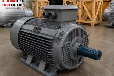
The shaft end is the cylindrical section of the motor rotor that extends beyond the housing and to which the drive element (coupling, pulley, gear, sprocket) is attached. This region both transmits rotational torque and carries the radial and axial loads created by the connected element. In cast iron body motors the shaft is usually machined from high-strength steel (C45 or similar) and precisely centered in the cast iron bearing housings. The cast iron shaft combination reduces fatigue risk at the shaft end, especially in variable-load applications, thanks to the natural vibration damping of cast iron.
There are four basic parameters at the shaft end and each must be selected correctly: diameter, length, diameter tolerance and keyway. In addition, the front face of the shaft end carries a DIN 332 center hole, and in some motors a threaded mounting hole bored along the shaft axis. The shaft diameter is determined by the standard IEC axis height (frame size) values; for a mid-size frame, the shaft diameter must match the standard IEC table value so it can directly mate with off-the-shelf couplings and pulleys.
DIN 332 Center Hole (Lathe Center) Forms
The DIN 332 center hole is the conical centering bore drilled axially into the front face of the shaft end. Though it looks like a minor detail at first glance, this hole serves two main functions. First, it allows the shaft to be machined between two centers on a lathe or grinding machine, enabling the shaft end to be produced with high concentricity. Second, in field coupling or pulley mounting it provides a connection point for centering and axial fixing (for example a ball center or a thrust bolt) from the shaft face. The DIN 332 standard defines several different forms:
- Form A: Unprotected, basic center hole with only a conical surface. The most common form for machining purposes; used where no threaded connection is required.
- Form B: In addition to the conical surface it includes a protective chamfer (60-degree cone + protective 120-degree chamfer). Preferred on precision shafts where the center surface must be protected from impact and burrs.
- Form C: Radiused (rounded) center hole; used on dynamically loaded shafts where reduced stress concentration is desired.
- Form R: Fully radiused profile; for very precise machining and low stress concentration cases.
- Form D / DS / DR: Threaded center hole. An M-type thread is cut into the shaft-end face, so a coupling or pulley can be clamped axially with an M bolt from the face. This form prevents the element from sliding back off the shaft in heavy coupling installations.
In practice the motor shaft is most often supplied with Form B or a threaded form (D family). If your application requires pulling and seating the coupling or pulley axially with a bolt from the shaft face, you must request a shaft end with a threaded center hole. Stating this detail at the ordering stage eliminates the need for field drilling and any mounting delays.
Shaft Diameter, Length and Tolerance Selection (j6 / k6)
The diameter tolerance of the shaft end determines the type of fit for the element going over it. The two most common tolerances are j6 tolerance and k6. The j6 tolerance provides an interference between light press and transition fit; it is the default choice on standard motor shafts and allows the coupling/pulley to be fitted and removed by hand or with light pressing. The k6 gives a tighter fit; it is used in high-speed, vibrating or impact-loaded applications to prevent the element from loosening on the shaft.
In standard IEC motors, small frames usually use j6, while larger diameters mostly use j6 or k6. A tolerance class expresses different micron ranges depending on the nominal shaft diameter; therefore a designation like "shaft 28 j6" defines both the diameter and the permitted deviation band together. The shaft length is also determined proportionally to the diameter per IEC; a longer shaft end (for example the double-shaft option) is preferred when an additional drive or encoder connection is needed.
- j6 tolerance: General-purpose, removable coupling/pulley mounting; default on standard motors.
- k6 tolerance: Tighter fit; against loosening in high-speed and vibrating applications.
- Shaft length: Selected according to the hub width of the element to be mounted and the axial fixing allowance; a short shaft can cause the keyway not to seat fully.
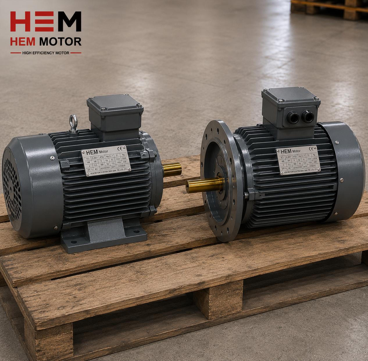
- Double shaft end: A shaft end on both sides may be requested in systems needing both drive and feedback (encoder/brake).
Correct tolerance selection directly affects coupling alignment quality. A too-loose fit creates vibration and noise, while a too-tight fit makes assembly/disassembly difficult and can damage the shaft. Our content on radial and axial load limits on the electric motor shaft is a complementary resource for those who want to combine shaft-end selection with load calculation.
Keyway (DIN 6885) and Torque Transmission
The keyway is the rectangular slot machined into the shaft end in which a standard key seats. The DIN 6885 standard defines key width, height and slot depth according to shaft diameter. The key transmits torque from the shaft to the drive element by form-fit, providing reliable transfer without relying on friction. In cast iron body motors the keyway is usually milled, and the slot corners are left slightly radiused to prevent fatigue cracking.
The length of the keyway must match the shaft-end length; the entire coupling or pulley hub should be supported by the key. Insufficient key length causes the key to brinell under load and the shaft end to wobble. In applications where high torque transmission is critical, key material and tight fit should be evaluated together. Our content on double shaft and key option with custom shaft order on IE4 motors details how to plan non-standard key and shaft-end requests.
Shaft-End Machining and Grinding Quality
Shaft-end machining covers turning the raw shaft, milling the keyway, drilling the threaded hole, and finally grinding the diameter surface. Grinding lowers the surface roughness of the shaft end so that the coupling/pulley seats to the true tolerance. A well-ground shaft end both guarantees fit quality and prevents dynamic balance disturbance during rotation. DIN 332 center holes are needed precisely so that this grinding can be done between two centers; a shaft without a center hole cannot be ground to high concentricity.
The rigidity provided by the cast iron body reduces shaft deflection in the bearings during grinding and makes it easier to reach lower surface tolerance. When shaft-end machining quality is low, vibration can appear even on a perfectly aligned coupling in the field; therefore machine precision and center-hole integrity in shaft-end production are direct indicators of product quality.
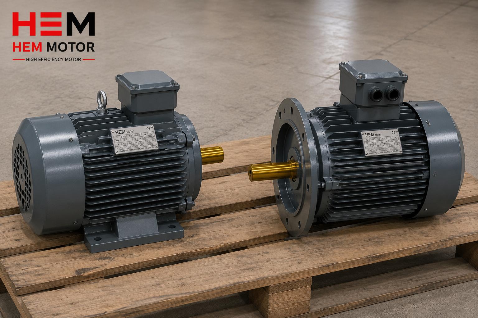
Correct Shaft Selection for Coupling, Pulley and Bearing Mounting
The shaft-end expectation changes with the drive element. In coupling mounting, face centering and axial fixing of the shaft matter; therefore a threaded center hole (Form D family) and proper tolerance stand out. Although flexible couplings tolerate some alignment error, correct shaft-end geometry fundamentally reduces vibration. Our content on flexible and rigid coupling selection with shaft alignment should be read together for coupling selection and alignment details.
In pulley (belt-pulley) mounting, the radial load is dominant; the pulley forces the shaft sideways. In this case the shaft-end length, keyway strength and shaft diameter tolerance must be selected to carry the radial load safely. The pulley hub must seat fully on the shaft end and be supported along the keyway. Bearing (support/pillow-block) mounting comes into play in applications where the shaft is supported by an intermediate bearing; here the concentricity and surface quality of the shaft are critical, and the precise shaft end machined thanks to the center hole ensures the support bearing runs smoothly.
- For coupling: Threaded center hole + j6/k6 tolerance + sufficient keyway length.
- For pulley: Shaft diameter suited to radial load, fully supported keyway, tighter fit if needed.
- For bearing/support: High concentricity, ground surface, DIN 332 center-hole integrity.
- In all cases: The rigidity of the cast iron body extends shaft-end life by damping vibration.
Sourcing the Right Shaft-End Option with HEM Motor
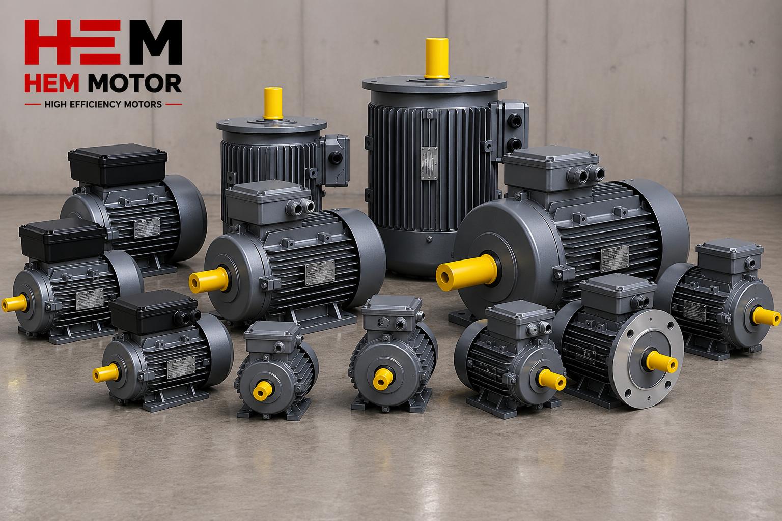
HEM Motor manufactures cast iron body electric motors with standard and custom shaft-end options under manufacturer assurance. Motors with a standard j6-tolerance shaft end, DIN 6885 keyway and DIN 332 center hole can be sourced quickly from stock, while requests such as a threaded center hole, double shaft, k6 tight fit or custom shaft length are met through custom production. When you specify the coupling, pulley or bearing mounting in your application, we clarify the correct shaft-end configuration together. To review the cast iron product family see our cast iron electric motors product group and for the general technical framework our advantages of cast iron body motors page. For current stock and quotation you can contact us through our electric motor prices page.
Correct shaft-end selection is the final link that ensures the motor's catalog rated values are fully reflected in the field. When tolerance, keyway, center-hole form and grinding quality are evaluated together, both mounting time is shortened and the life of the drive train is extended. Wherever you have a doubt about the shaft end, simply share your application data; we plan the rest as the manufacturer.
Frequently Asked Questions
Does every motor shaft have a DIN 332 center hole?
Most quality manufacturers drill a DIN 332 center hole so the shaft end can be ground between two centers, so it is generally present on machined shafts. However, a threaded (Form D) center hole is not standard and must be specified separately in the order if you want to fix the coupling axially with a bolt from the face.
Should I choose j6 or k6 tolerance for a coupling?
For general-purpose, removable mounting, j6 tolerance is sufficient and standard. If there is high speed, vibration or impact load, the k6 tight fit is more suitable to prevent the element from loosening on the shaft. Telling us your application load makes the correct tolerance selection easier.
Why is shaft-end length important in pulley mounting?
A pulley applies radial load; to carry this load safely, full support along the keyway and sufficient shaft end length are required. With a short shaft end the pulley hub does not seat fully, which can lead to wobble and early fatigue.