English
 Türkçe
The cable run between a frequency drive (VFD) and a motor looks at first glance like a passive connection that merely carries electricity. Yet the pulsed (PWM) voltage produced on the drive side behaves like a transmission line as it travels along this cable, and once the cable exceeds a certain length it can cause voltage overshoots at the motor terminals far above the supply voltage. This phenomenon, namely voltage reflection, is one of the most common causes that quietly fatigues winding insulation while going unnoticed in the field. In this article we examine VFD-to-motor cable length with voltage reflection, dv/dt and filter solutions, explaining how to source the right motor-drive.
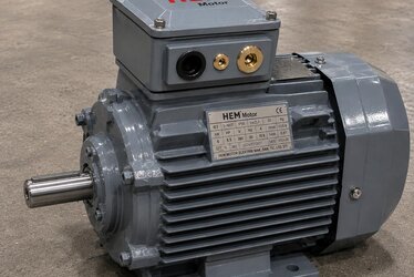
At HEM Motor, we recommend motors that will run with a frequency drive taking cable length and drive compatibility into account as well. Because in a drive-fed system the motor's life depends not only on the motor's quality but also on the waveform that reaches the motor. The right cable, the right filter and the right insulation strength are a whole.
Why Does Voltage Reflection Occur?
Modern frequency drives produce their output voltage as pulses with very fast edges (short rise time). These fast edges carry high-frequency components. The cable behaves like a transmission line between the drive's output impedance and the motor's input impedance. When the impedances at the two ends do not match, the pulse reflects back when it reaches the motor terminal; the incoming wave and the reflected wave superimpose and can create voltage peaks at the motor terminals approaching nearly twice the supply voltage.
The severity of this event depends on three factors: cable length, the pulse rise time (edge steepness) and the degree of impedance mismatch. The longer the cable and the steeper the edge, the higher the voltage peak at the motor terminals.
What Is dv/dt and Why Is It Important?
dv/dt is the rate of change of voltage with time; that is, it expresses how steep the pulse edge is. High dv/dt causes uneven voltage distribution across the first few turns of the winding; this disproportionately stresses the insulation in that region. Over time this stress can lead to partial discharges and ultimately insulation breakdown. High voltage peaks and high dv/dt together are the leading cause of winding failures in drive-fed systems.
Why Does Cable Length Set a Critical Threshold?
On short cables the reflected wave returns before the pulse reaches its peak value and causes no problem. However, once the cable exceeds a certain critical length, the reflected wave superimposes with just the right timing and the voltage peak reaches its maximum. This critical length depends on the pulse rise time: the steeper the edge, the shorter the critical length. So the same cable length, while problem-free on one drive, can cause problems on another drive with steeper edges.
The practical result is this: as the distance between the VFD and the motor increases, the voltage stress at the motor terminals also increases. For this reason a measure must always be taken in long-cable installations. We covered when a frequency drive is needed and how to select it in our frequency drive with asynchronous motor article.
Application Examples: Where Does Distance Become a Problem?
Voltage reflection comes to the fore in installations where the cable distance is long. The scenarios most frequently encountered in the field are:
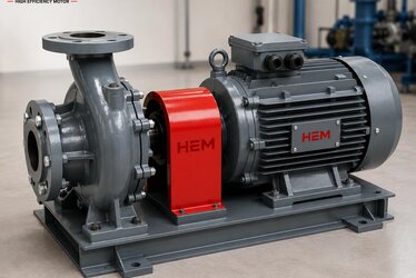
- Pump/fan groups far from the panel room: When the drives are in a central panel room and the motor is in a distant corner of the plant, the cable lengthens. This is common in water pump stations and ventilation groups.
- Submersible and deep-well pumps: When the motor is meters below and the drive above, the cable is naturally long; voltage stress must be seriously considered in these applications.
- Open-site and long-line conveyors: When the physical distance between drive and motor is large, the cable lengthens.
- Retrofit installations: When a drive is added later to an existing plant, the cable route may already be long, and since re-routing is costly, a filter solution comes to the fore.
In these scenarios, knowing the cable distance from the start when selecting the motor enables the right insulation and filter decision. When distance is noticed later, the solution becomes both more expensive and more troublesome.
Solutions: Filters and Insulation Strength
There are several complementary approaches against the voltage stress caused by long cable distance. The right solution is chosen according to cable distance, drive type and the motor's insulation strength.
1. Motor Output Reactor (Output Choke)
A reactor placed at the drive output softens the pulse edge; it lowers dv/dt. It is an economical and effective first measure in medium-distance installations. It does not fully eliminate the voltage peak but pulls it to an acceptable level.
2. dv/dt Filter
This is a more comprehensive solution than the reactor; by notably extending the pulse rise time it limits both dv/dt and the voltage peak. It is preferred to protect the winding over long cable distances.
3. Sine Filter
This is the most comprehensive solution; it converts the drive's pulsed output into an almost clean sine wave. The motor thus sees a smooth voltage as if fed directly from the grid. It is used over very long cable distances, in noise-sensitive environments and in critical applications where maximum winding protection is desired. We separately covered the output sine filter on the IE5 synchronous reluctance motor in our IE5 output sine filter article.
4. Inverter Duty Insulation
The measure to take on the motor side is reinforced winding insulation. The insulation system of motors that will run with a drive must be selected to withstand high voltage peaks and high dv/dt. This complements the filter solutions; in an ideal installation the motor has suitable insulation and, if needed, a filter is used. At HEM Motor we consider insulation strength from the very start in motors that will run with a drive, ensuring the motor is ready for the drive environment with Class F insulation and a quality winding structure.
Filter Mounting Location and Heating
Filters are also heat-generating elements; they must be placed in a properly ventilated location inside the panel. Mounting them as close to the drive output as possible increases the effectiveness of the protection. A ventilation plan must be made from the start so that the heat the filter dumps does not raise the panel internal temperature. A wrongly positioned filter both shortens its own life and stresses the other elements in the panel.
Signs of Voltage Stress: How to Detect It in the Field
The damage from voltage reflection usually appears not suddenly but by accumulating over time. For this reason, recognizing the signs enables taking measures before the problem grows.
- Recurring winding failures: Motors burning their windings earlier than expected in the same application can point to a long cable + filterless drive combination.
- Stress in the first turns: Winding failure mostly begins in the first turns at the phase input; this is a typical trace of high dv/dt.
- Abnormal heating and noise: High-frequency components can create extra loss and heating.
- Stress marks at terminal ends: High voltage peaks can leave marks on insulation surfaces over time.
When these signs are seen, the cable distance and filter status must be reviewed before replacing the motor; otherwise the new motor is exposed to the same stress.
The Filter Selection Distance-Solution Logic
Which solution is needed depends largely on cable distance and drive output characteristics. The general logic can be summarized as follows:
- Short distance: A motor with inverter duty insulation is usually sufficient; in most cases no extra filter is needed.
- Medium distance: An output reactor or dv/dt filter keeps the voltage peak within a safe limit.
- Long distance: A dv/dt filter or, in a critical case, a sine filter is recommended.
- Very long distance / critical protection: A sine filter provides maximum protection by converting the output to a clean sine.
These thresholds vary by drive type; therefore distance and drive data must be evaluated together. The right solution is striking the balance that is not unnecessarily expensive yet protects the winding sufficiently.
The Right Cable: Not Just Distance
In the VFD-motor connection, the cable itself also matters. In drive-fed systems, using shielded cable is important both for managing voltage reflection and for electromagnetic compatibility (EMC). Correctly grounding the shield at both ends is necessary for controlling high-frequency noise and bearing currents. We covered grounding and EMC connection in detail in our grounding and EMC VFD system connection article.
- Shielded cable: Reduces noise and bearing current risk.
- Correct cross-section: Selected by current-carrying capacity and voltage drop.
- Proper grounding: A 360-degree termination of the shield is ideal.
- Cable route: The drive cable must be kept separate from signal cables.
Bearing Currents: The Other Benefit of Cable and Filter
Besides voltage reflection, another risk in drive-fed systems is bearing currents. The high-frequency common-mode voltage produced by the drive creates a voltage on the motor shaft; this voltage can puncture the bearing oil film and cause micro-arc currents, creating fluting damage in the bearing over time. The right shielded cable, proper grounding and, where necessary, an insulated bearing or shaft grounding brush manage this risk. dv/dt and sine filters indirectly lower the bearing current risk too by reducing high-frequency content. So the right filter and cable selection protect both the winding and the bearings; the two problems feed from the same root.
Sourcing the Right Motor-Drive: A System Approach
The VFD-motor cable distance problem arises from thinking of the motor, drive, cable and filter separately. The right approach is to treat them as a single system. At HEM Motor we question the cable distance and drive type in drive-fed applications; accordingly we recommend the motor's insulation strength and, if needed, the filter solution together.
To Be Determined Before Sourcing
- The estimated cable length between drive and motor.
- The drive type and output edge steepness (manufacturer data if available).
- The motor's operating environment and EMC requirements.
- The winding insulation strength (is it inverter duty?).
- The cable type to be used (shielded?).
To determine the motor-drive combination and filter solution suitable for your application, you can review our product range for current electric motor prices and configuration options. We also covered extra heating from harmonics and bearing currents in drive-fed systems in our VFD harmonic heating and bearing current article.
Commissioning and Verification
When a drive-fed system is commissioned, it is ideal to verify that the voltage stress caused by the cable distance is within an acceptable limit. This includes setting the drive and filter parameters per application. The following points should be reviewed at commissioning: correct separation of the cable route, proper shield grounding, suitability of the filter mounting and ventilation, and the motor's heating behavior. These checks ensure the system runs safely not only on the first day but for years. We covered drive-side compatibility and commissioning steps with a holistic checklist in our drive and installation compatibility commissioning article.
The Right Choice from a Total System Cost Perspective
A filter and inverter duty insulation look like an extra cost in the initial investment; yet the hidden cost of a long filterless cable installation is far higher. Early winding failure, unplanned downtime, production loss and recurring motor replacement cost are many times the right measure taken from the start. For this reason, when designing a VFD-motor system, cable distance must be considered at the very beginning and, if needed, the filter solution included in the initial investment. A correctly designed system both extends the motor's life and lowers the total cost.
Frequently Asked Questions
My cable distance is short; is a filter still needed?
At short cable distances voltage reflection usually does not reach a problematic level, so in most cases no filter is needed. However, this also depends on the drive's output edge steepness; on drives with very steep edges the critical distance shortens. Still, the motor having inverter duty insulation is a safe choice in any case. Distance and drive type must be evaluated together.
Should I choose a sine filter or a dv/dt filter?
A dv/dt filter may be sufficient over medium-long distances to limit the voltage peak and edge steepness. A sine filter provides the highest level of protection by converting the output to a clean sine; it is preferred where very long distance, noise sensitivity and critical motor protection are needed. The choice is made according to cable distance, drive type and the priority of protection; we listen to your application and determine the right solution together.
Does buying an inverter duty motor eliminate the need for a filter?
Inverter duty insulation increases the motor's resistance to voltage peaks and provides extra protection in many installations; however, over very long cable distances it may not be sufficient on its own. The ideal approach is for the motor to have suitable insulation and be supported by a filter if the distance requires it. The two complement each other; one does not always substitute for the other.