English
 Türkçe
A metalworking or CNC machining plant looks from the outside like a single cluster of machines; inside, however, dozens of electric motors run with very different drive requirements. The torque demand of the motor turning a chip conveyor, the continuous-duty load of the motor driving a coolant pump, and the speed behavior of the drive motor feeding a machine tool spindle are completely separate worlds. For this reason, electric motor selection for a metalworking plant must not follow a single recipe but be made according to the duty profile of each subsystem. A wrongly chosen motor leads to chip jams, coolant interruptions, unexpected stoppages and energy waste. In this guide we examine the three main motor groups of a CNC machining plant — chip conveyor, coolant pump and machine tool drive — separately, and explain how to determine the right frame, mounting type, protection class and efficiency class. Our goal is to help you choose long-lived motors that will not stop your production line and can be supplied quickly from stock.
The Environment Motors Face in a CNC Plant: Chips, Coolant and Mist
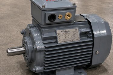
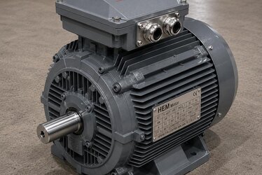
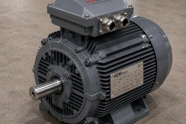
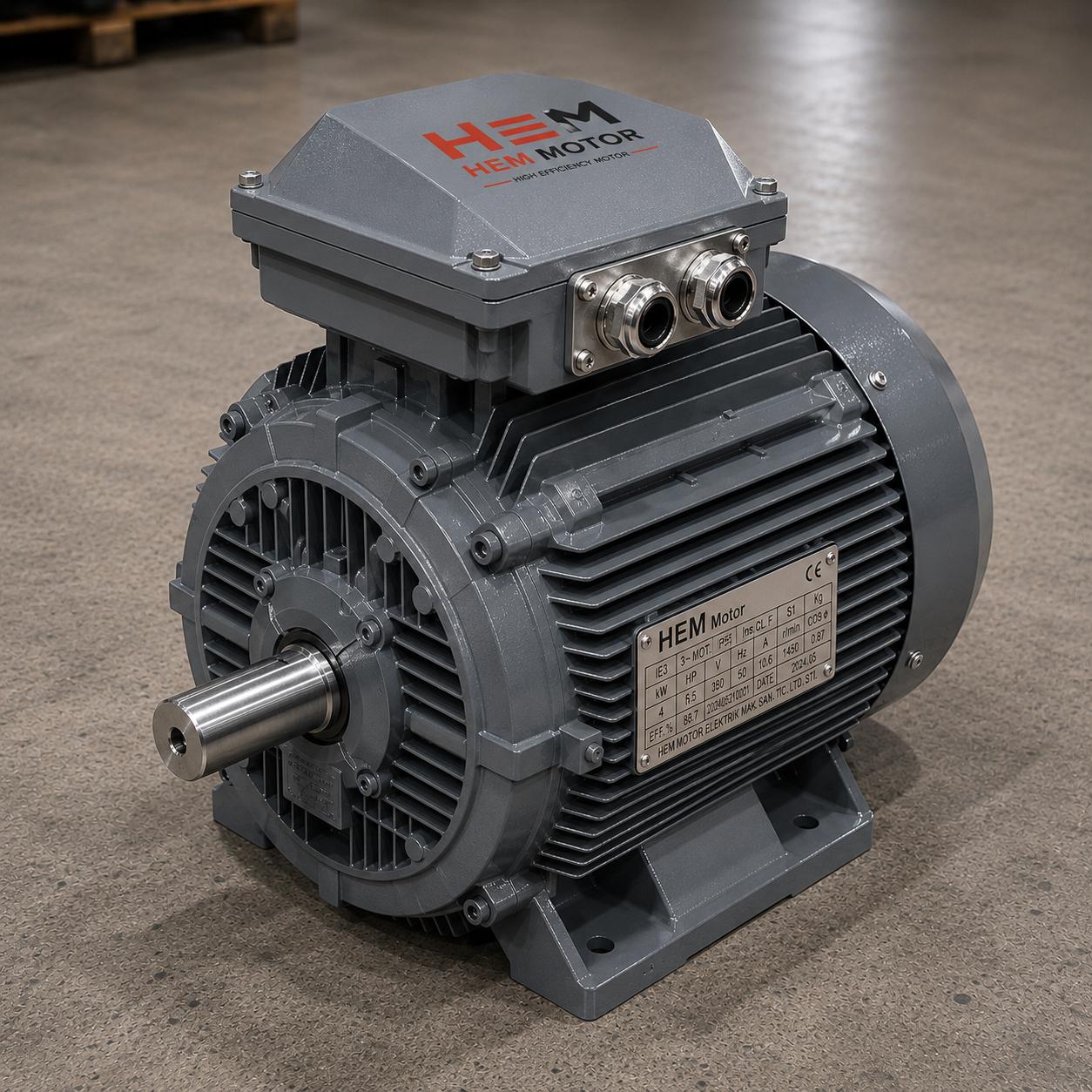
Metalworking plants are a harsh environment for electric motors. Hot chips flung from the machines, continuously flowing coolant (cutting fluid), oil-water mist in the air and fine metal dust all settle on the motors. Therefore at least IP55 protection class is essential almost everywhere in the plant; where coolant sprays directly or the motor stays in a wet zone, IP56 or higher protection is preferred. HEM Motor motors are produced as standard with IP55 protection and Class F insulation, which directly meets the basic expectation of a machining environment.
Housing material is also a critical choice here. Cast iron body motors withstand the impact of flying chips and heat better than aluminum; in heavy-duty conveyors and continuously running pumps a cast iron housing provides long life. Aluminum housings can be chosen for compact and lighter applications, but cast iron stands out in zones where chip and fluid loads are heavy.
Chip Conveyor Motor: Torque Is the Priority
The chip conveyor is a critical subsystem that collects chips leaving the machine and carries them out. The most important feature of the motor here is not high speed but high starting torque and continuous torque. The conveyor belt or auger must make its first movement under heavy load together with the chips accumulated on it; that is why conveyor motors are mostly used together with a gear reducer.
Geared Drive and the Need for Low Speed
A chip conveyor must have low output speed and high torque. Therefore a 1500 rpm motor is connected to the conveyor not directly but through a worm gear reducer or helical bevel reducer. Points to watch in motor selection:
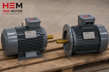
- A flange-mounted (B5 or B14) or combined (B35) frame suited to the reducer enables direct coupled connection.
- 1000 rpm or 1500 rpm motors suit conveyor applications that need higher torque.
- A cast iron housing withstands the sudden load surge that occurs during a chip jam.
- S1 continuous duty and Class F insulation support uninterrupted operation throughout the shift.
To keep the motor from being overstressed during a chip jam, correct power-torque matching must be done; an undersized motor draws excessive current continuously and shortens its life through overheating.
Coolant Pump Motor: Continuous Duty and Efficiency
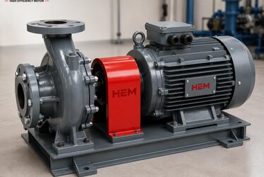
The coolant (cutting fluid) pump is a vital component that cools the cutting zone and washes away chips in a CNC machine. This pump turns without interruption as long as the machine runs; that is, its motor typically carries load under continuous duty (S1) for long hours each day. The two prominent criteria here are efficiency and protection against fluid.
Why Is a High Efficiency Class Important?
A continuously running pump motor accumulates very high operating hours throughout the year. Therefore choosing an IE3 or preferably IE4 efficiency class motor makes a clear difference on the energy bill. A high-efficiency motor that does the same work with fewer losses pays for itself over time through energy savings. Points to watch in pump motors:
- Flange (B5/B14) mounting is ideal for direct connection to centrifugal pumps; it suits vertical and horizontal systems.
- IP55 and higher protection shields the motor against coolant splash and mist.
- 3000 rpm motors are preferred for high-pressure fluid applications, 1500 rpm motors for a more balanced and quieter flow.
- 100% copper winding improves heating behavior under continuous load and extends life.
Machine Tool Drive and Auxiliary Axes: Speed and Control
The spindle drive and auxiliary axis motors of a CNC machine are the plant's most precise drive group. There is usually a need for variable speed here; the motor works together with a variable frequency drive (VFD) to adapt to different cutting speeds. The auxiliary systems around the machine — hydraulic units, lubrication pumps, cooling fans — are also fed by separate motors.
- On motors that will run with a drive, Class F insulation and suitable thermal protection are important against heating at variable speed.
- Auxiliary hydraulic unit motors should be suited to continuous duty, resistant to heating and low in vibration.
- For cooling fans, low vibration and quiet operation are valuable for the comfort of the working environment.
- B3 foot-mounted frames are chosen for general purpose applications, flange frames for those to be connected to a reducer.
Plant-Wide Motor Standardization and the Stock Advantage
While dozens of different motors run in a CNC plant, consolidating as much as possible around standard frames and power ratings makes spare parts management easier. Stocking a few spare motors of the same frame size restarts production in minutes rather than hours when a failure occurs. As HEM Motor we support this standardization strategy by supplying common power and frame ratings from stock and special needs on short lead times.
- Fast delivery from stock at commonly used powers shortens unplanned downtime.
- Standardization on the same mounting type and frame size lowers spare motor cost.
- Motors purchased with manufacturer assurance, with clear nameplate and connection dimensions, cause no compatibility issues during replacement.
To determine the right motor configuration for your plant's chip conveyor, coolant pump and machine tool drive, and to get information on current electric motor prices and stock availability, you can contact us. For your pump applications you can review our pump electric motors, for your chip handling systems our conveyor belt electric motors, for high-efficiency continuous duty our IE4 electric motors and for general plant needs our high-efficiency electric motors product families.
Power and Speed Selection: The Right Combination by Duty Profile
For each motor in a metalworking plant, the right power and speed combination determines both energy efficiency and long life. An oversized motor runs continuously at partial load; this both raises the initial investment and causes efficiency loss at low load. An undersized motor, on the other hand, continuously draws excess current, overheats and tires the winding insulation over time. The right choice is a balanced power-speed match according to the duty profile.
Distribution of Speed Options by Application
- 3000 rpm (2-pole): Suitable for high-pressure coolant pumps, compact fans and auxiliary applications that require high speed.
- 1500 rpm (4-pole): The most common speed; it offers a balanced choice for conveyor drives, general pump applications, hydraulic units and many auxiliary systems.
- 1000 rpm (6-pole): Preferred for heavy conveyor and mixing applications that require higher torque and lower output speed.
In plant design, setting the speed choice directly according to the output speed required by the driven machine reduces intermediate transmission losses. At points where a reducer is used, the motor speed and reducer ratio must be calculated together; the desired output speed is obtained from the product of these two values.
Mounting Type Selection: B3, B5 and B35
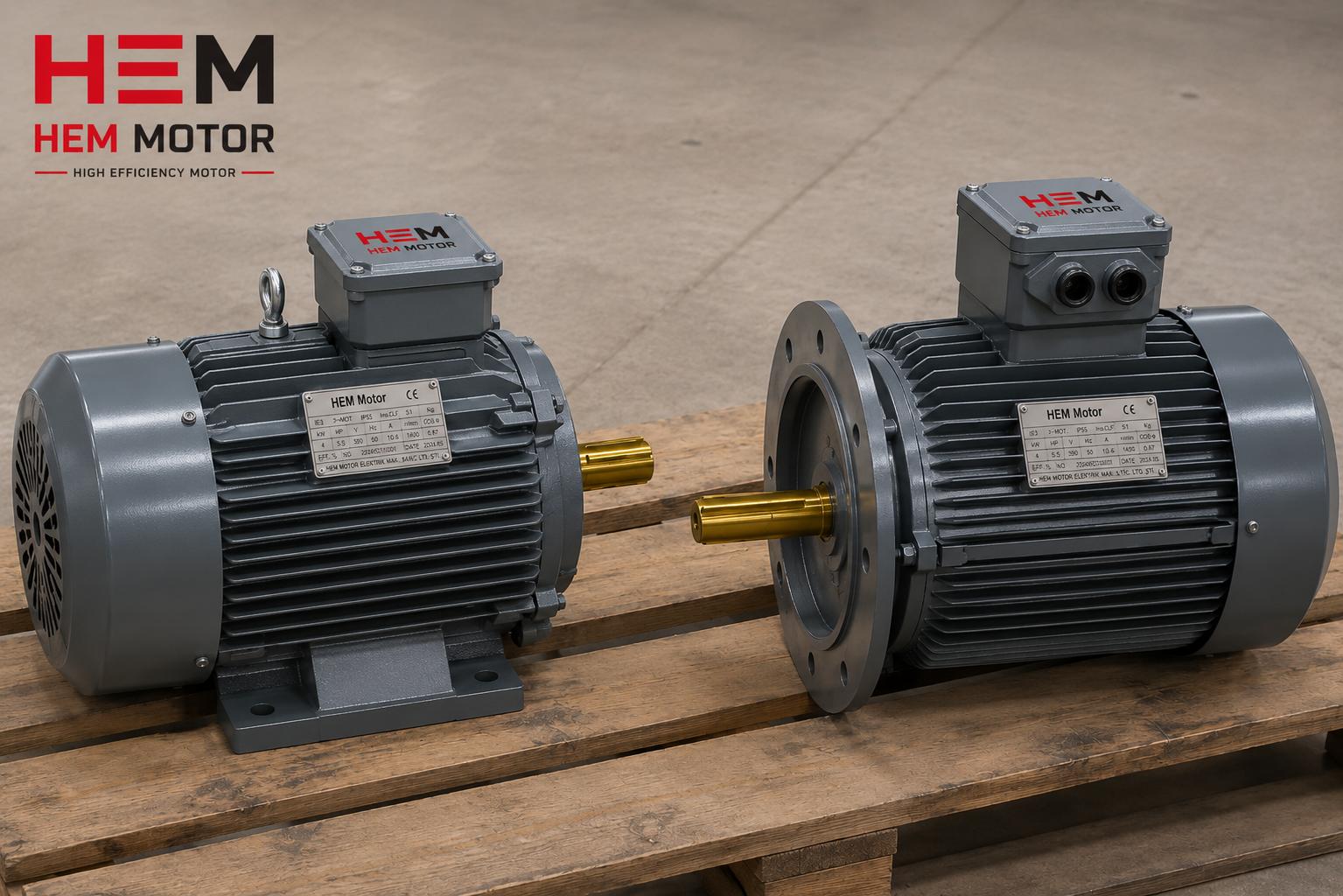
In a metalworking plant, how the motor connects to the machine begins with the right mounting type choice. The wrong mounting type leads to incompatibility and delay on site. The HEM Motor range meets the connection needs of every corner of the plant with B3 foot, B5 large flange, B14 small flange and B35 combined mounting options.
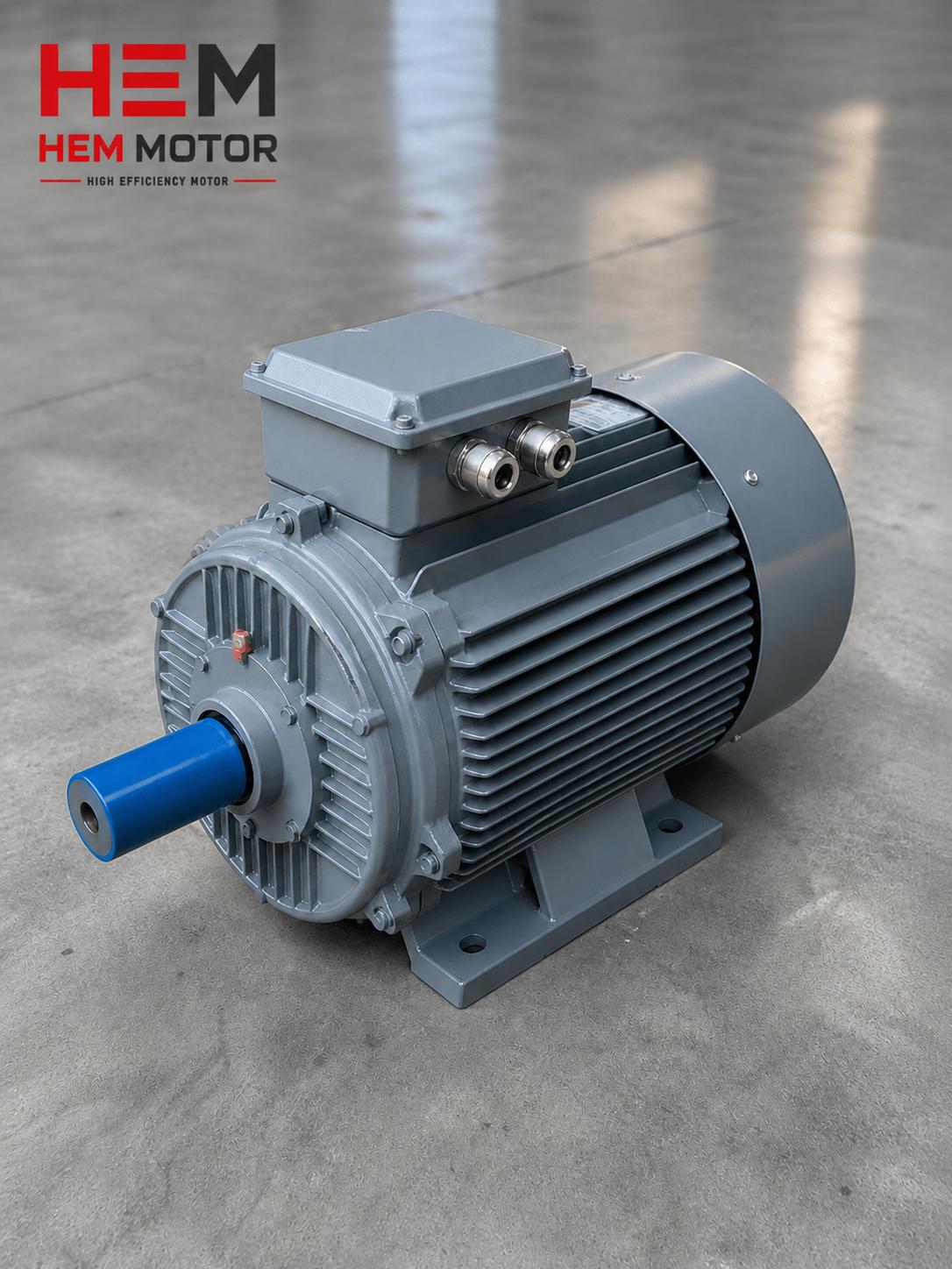
- B3 (foot-mounted): Bolted to the floor, base or frame; the most common mounting type, used in belt-pulley or coupled drives.
- B5 (large flange): Connected directly to the pump and reducer via the flange; ideal in coolant pumps and geared conveyor drives.
- B35 (foot + flange): Connected both to the frame by feet and to the machine by flange, providing the highest mechanical stability; preferred in heavy conveyor and vibrating applications.
Clearly stating the mounting type, shaft diameter and flange dimensions at the ordering stage ensures that a perfectly compatible motor arrives correctly the first time; this eliminates unplanned delays.
Planned Maintenance and Spare Motor Strategy
In metalworking plants, an unplanned motor failure stops not just a single machine but often the entire production flow. A proactive approach is therefore needed for critical drives. Keeping a spare for continuously running coolant pumps and conveyor motors prevents production from waiting hours during a failure. Since the heating behavior of high-efficiency, 100% copper-wound motors is more predictable, maintenance planning is also easier.
- Stocking at least one spare motor of the same frame and power for critical drives minimizes downtime.
- Regularly monitoring bearing and winding temperature provides an early warning before failure.
- For motors purchased with manufacturer assurance, spare supply and technical support are continuous; nameplate and connection data can be archived.
Frequently Asked Questions
Why is torque, not high speed, important in a chip conveyor motor?
A chip conveyor must make its first movement together with the heavy chips accumulated on it, which requires high starting torque and continuous torque. Since high speed is not needed, the motor is usually connected through a reducer; low output speed and high torque are obtained. For this reason, besides power, the reducer ratio and flange mounting compatibility take priority in selection.
What protection class is needed in a coolant pump motor?
In an environment where cutting fluid splashes continuously and forms mist, at least IP55 protection class is needed. Where the motor stays directly under fluid or there is heavy spray, IP56 or higher protection should be preferred. Also, due to continuous operation, a high efficiency class and 100% copper winding extend life by reducing heating.
Why is consolidating plant motors around standard power and frame advantageous?
Standardization makes it possible to stock a few spare motors of the same frame size; when a failure occurs production restarts in minutes rather than hours. Spare parts and installation cost also fall. Motors bought from HEM Motor with manufacturer assurance, with clear nameplate and connection dimensions, make this standardization easier.